How to configure cell battery and USB power

Hi to all,

this is my first public ticket ;)

I would power a nRF52840 on my custom board both with a cell battery (specifically CR2032) and the VBUS provided by the USB connection.
I was thinking to use two schottky diode in the way showed in the attached image with using the internal DCDC of the nRF52840 as in the development board.

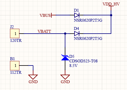
But I'm not sure to use schottky diode since the voltage drop on the diode. In the proposed configuration for the nRF52840, I cannot find any solution that could fit with this question.

Has anyone done this task before?

Thanks in advance

Parents Reply
  • Ah, good point. 3 x 47uF are not that big but I see the problem. 2 x 4.7uF will shorten the useable coin cell battery life, perhaps by 10%, as more of the pulse current has to be supplied from the coin rather than the coin trickle-charging the capacitors and the risk of current-pulse-induced nRF52840 resets will occur sooner. Mitigate by using PPI and keeping the CPU in sleep as much as possible and set VDD to 2.8V. Rapid advertising Tx burst raise the risk of resets, reducing the attempts will also help; instead of (say) 20 Tx advertising per second 1 per second is much better even if then it takes longer to connect. Ditto in Beacon Mode. Worst case change the design to use an  external DC-DC battery-to-VDD at 1.8V instead of 2.8V, but that takes as much physical space as 3 x 47uF.

Children
No Data
Related