Hi,
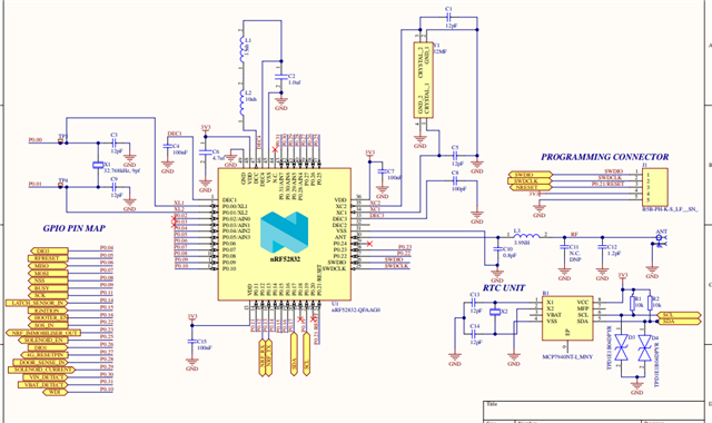
I'm working on a custom board with nrf52832 and I'm running into an issue where the firmware will only run on the custom board in debug. But it works fine in nrf52DK. For my build configuration I'm using nrf52dk/nrf52832 board. below is my prj.conf
#
# Copyright (c) 2018 Nordic Semiconductor
#
# SPDX-License-Identifier: LicenseRef-Nordic-5-Clause
#
CONFIG_NCS_BOOT_BANNER=n
CONFIG_BOOT_BANNER=n
CONFIG_BOOT_DELAY=0


CONFIG_BT=y
CONFIG_BT_PERIPHERAL=y
CONFIG_BT_DEVICE_NAME="IK_MB_LBS"
CONFIG_BT_MAX_CONN=2
# Enable the LBS service
# CONFIG_BT_LBS=y
# CONFIG_BT_LBS_POLL_BUTTON=y
# CONFIG_DK_LIBRARY=y
CONFIG_BOARD_ENABLE_DCDC=n

CONFIG_BT_BUF_ACL_RX_SIZE=251
CONFIG_BT_BUF_ACL_TX_SIZE=251
CONFIG_BT_L2CAP_TX_MTU=247
CONFIG_BT_CTLR_DATA_LENGTH_MAX=251

CONFIG_SYSTEM_WORKQUEUE_STACK_SIZE=2048

# CONFIG_SERIAL=y
CONFIG_UART_ASYNC_API=y

# CONFIG_GPIO=y
CONFIG_ADC=y

CONFIG_BOOTLOADER_MCUBOOT=y
CONFIG_NCS_SAMPLE_MCUMGR_BT_OTA_DFU=y


CONFIG_FLASH=y

CONFIG_NVS=y
CONFIG_REBOOT=y
CONFIG_MPU_ALLOW_FLASH_WRITE=y
CONFIG_PM_PARTITION_SIZE_SETTINGS_STORAGE=0x4000
CONFIG_SETTINGS_NVS_SECTOR_COUNT=2

CONFIG_I2C=n
CONFIG_SPI=n
CONFIG_WATCHDOG=n
CONFIG_THREAD_STACK_INFO=n
CONFIG_THREAD_CUSTOM_DATA=n
CONFIG_FPU=n
CONFIG_LOG=n
CONFIG_PRINTK=n

CONFIG_NFCT_PINS_AS_GPIOS=y
my overlay file
// To get started, press Ctrl+Space to bring up the completion menu and view the available nodes.

// You can also use the buttons in the sidebar to perform actions on nodes.
// Actions currently available include:

// * Enabling / disabling the node
// * Adding the bus to a bus
// * Removing the node
// * Connecting ADC channels

// For more help, browse the DeviceTree documentation at https://docs.zephyrproject.org/latest/guides/dts/index.html
// You can also visit the nRF DeviceTree extension documentation at https://docs.nordicsemi.com/bundle/nrf-connect-vscode/page/guides/ncs_configure_app.html#devicetree-support-in-the-extension
/ {

	gpio_output {
		compatible = "gpio-leds";
		solenoiden: solenoid_en {
			gpios = <&gpio0 25 GPIO_ACTIVE_LOW>;
			label = "solenoid Enable";
		};
		ec200ureset:ec200u_reset{
			gpios = <&gpio0 27 GPIO_ACTIVE_LOW>;
			label = "EC200U reset pin";
		};
		extwatchdog:ext_watchdof{
			gpios = <&gpio0 10 GPIO_ACTIVE_LOW>;
			label = "External watchdog pin";
		};
    };

	buttons{
		button0: button_0 {
			status="disabled";
		};
		button1: button_1 {
			status="disabled";
		};

		button2: button_2 {
			status="disabled";
		};

		button3: button_3 {
			status="disabled";
		};
	};

	leds {
		led0: led_0 {
			status="disabled";
		};
		led1: led_1 {
			status="disabled";
		};
		led2: led_2 {
			status="disabled";
		};
		led3: led_3 {
			status="disabled";
		};
	};

	gpio_input{
		compatible = "gpio-keys";
		doorsense: door_sense_in{
			gpios = <&gpio0 28 (GPIO_PULL_UP | GPIO_ACTIVE_LOW)>;
			label = "Door sense pin";
		};
		latchsense: latch_sense_in{
			gpios = <&gpio0 14 (GPIO_PULL_UP | GPIO_ACTIVE_LOW)>;
			label = "Latch sense pin";
		};
		ignitionin:ignition_in{
			gpios =<&gpio0 15 (GPIO_PULL_UP | GPIO_ACTIVE_LOW)>;
			label = "Ignition in pin";
		};
	};

    zephyr,user {
        io-channels = <&adc 5>,<&adc 6>,<&adc 7>;
    };
};
&spi2 {
    status="disabled";
};
/delete-node/ &{/pin-controller/uart0_default/group1/};
/delete-node/ &{/pin-controller/uart0_sleep/group1/};


&uart0_default {
    group1 {
        psels = <NRF_PSEL(UART_TX, 0, 13)>, <NRF_PSEL(UART_RX, 0, 12)>;
    };
};

&adc {
	#address-cells = <1>;
	#size-cells = <0>;
	status = "okay";
	channel@5 {
		reg = <5>;
		zephyr,gain = "ADC_GAIN_1_4";
		zephyr,reference = "ADC_REF_VDD_1_4";
		zephyr,acquisition-time = <ADC_ACQ_TIME_DEFAULT>;
		zephyr,input-positive = <NRF_SAADC_AIN5>;
		zephyr,resolution = <10>;
	};
	channel@6 {
		reg = <6>;
		zephyr,gain = "ADC_GAIN_1_4";
		zephyr,reference = "ADC_REF_VDD_1_4";
		zephyr,acquisition-time = <ADC_ACQ_TIME_DEFAULT>;
		zephyr,input-positive = <NRF_SAADC_AIN5>;
		zephyr,resolution = <10>;
	};
	channel@7 {
		reg = <7>;
		zephyr,gain = "ADC_GAIN_1_4";
		zephyr,reference = "ADC_REF_VDD_1_4";
		zephyr,acquisition-time = <ADC_ACQ_TIME_DEFAULT>;
		zephyr,input-positive = <NRF_SAADC_AIN5>;
		zephyr,resolution = <10>;
	};
};

&spi1{
	status="disabled";
};
&i2c0 {
	status="disabled";
};
&pwm0 {
	status="disabled";
};
My schematic

