
Hi there,
So I am using an adapted version of the echo sample for I2S in the nRF Connect SDK in VS Code. I only want to use the echo example in receiving mode, so I have removed the transmit data function calls. I am using the microphone SPH0465 with the nRF52832 (slave mode).
Here is my adapted example.
/*
 * Copyright (c) 2021 Nordic Semiconductor ASA
 *
 * SPDX-License-Identifier: Apache-2.0
 */

#include <zephyr/kernel.h>
// #include "codec.h"
#include <zephyr/sys/printk.h>
#include <zephyr/drivers/i2s.h>
#include <zephyr/drivers/gpio.h>
#include <zephyr/sys/util.h>
#include <zephyr/sys/printk.h>
#include <inttypes.h>
#include <zephyr/logging/log.h>
#include <zephyr/logging/log_ctrl.h>
#include <string.h>
#include <zephyr/drivers/pwm.h>
#include <zephyr/drivers/uart.h>


LOG_MODULE_REGISTER(MODULE, 3);


#if DT_NODE_EXISTS(DT_NODELABEL(i2s_rxtx))
#define I2S_RX_NODE  DT_NODELABEL(i2s_rxtx)
#define I2S_TX_NODE  I2S_RX_NODE
#else
#define I2S_RX_NODE  DT_NODELABEL(i2s_rx)
#define I2S_TX_NODE  DT_NODELABEL(i2s_rx)
#endif

#define SAMPLE_FREQUENCY    44100
#define SAMPLE_BIT_WIDTH    24
#define BYTES_PER_SAMPLE    sizeof(int32_t)
#define NUMBER_OF_CHANNELS  2
/* Such block length provides an echo with the delay of 100 ms. */
#define SAMPLES_PER_BLOCK   32
#define INITIAL_BLOCKS      2
#define TIMEOUT             1000

#define SW0_NODE        DT_ALIAS(sw0)
#if DT_NODE_HAS_STATUS(SW0_NODE, okay)
static struct gpio_dt_spec sw0_spec = GPIO_DT_SPEC_GET(SW0_NODE, gpios);
#endif

#define SW1_NODE        DT_ALIAS(sw1)
#if DT_NODE_HAS_STATUS(SW1_NODE, okay)
static struct gpio_dt_spec sw1_spec = GPIO_DT_SPEC_GET(SW1_NODE, gpios);
#endif

#define BLOCK_SIZE  (BYTES_PER_SAMPLE * SAMPLES_PER_BLOCK)
#define MAX_BLOCK_SIZE BLOCK_SIZE
#define BLOCK_COUNT (INITIAL_BLOCKS + 2)
K_MEM_SLAB_DEFINE_STATIC(mem_slab, BLOCK_SIZE, BLOCK_COUNT, 4);

static int16_t echo_block[SAMPLES_PER_BLOCK];
static volatile bool echo_enabled = true;
static K_SEM_DEFINE(toggle_transfer, 1, 1);

#if DT_NODE_HAS_STATUS(SW0_NODE, okay)
static void sw0_handler(const struct device *dev, struct gpio_callback *cb,
			uint32_t pins)
{
	bool enable = !echo_enabled;

	echo_enabled = enable;
	printk("Echo %sabled\n", (enable ? "en" : "dis"));
}
#endif

#if DT_NODE_HAS_STATUS(SW1_NODE, okay)
static void sw1_handler(const struct device *dev, struct gpio_callback *cb,
			uint32_t pins)
{
	k_sem_give(&toggle_transfer);
}
#endif


// PWM DEFINES
static const struct pwm_dt_spec pwm_led0 = PWM_DT_SPEC_GET(DT_ALIAS(pwm_led0));
static const struct pwm_dt_spec pwm_led1 = PWM_DT_SPEC_GET(DT_ALIAS(pwm_led1));

// // frequency for pwm1 module
// // Frequency: 4 MHz -> Period: 250 ns (1 / 4 MHz)
// // Duty cycle: 50% -> Pulse width: 125 ns

#define PERIOD_PWM1_NSEC PWM_NSEC(1000U)  // 250 nanoseconds for 4 MHz frequency
#define PULSE_WIDTH_PWM1_NSEC PWM_NSEC(PERIOD_PWM1_NSEC / 2U)  // 50% duty cycle, so pulse width is half the period

// // frequency for pwm0 module
// // Frequency: 62,500 Hz -> Period: 16 µs (1 / 62500)
// // Duty cycle: 50% -> Pulse width: 8 µs

#define PERIOD_PWM0_NSEC  PWM_NSEC(PERIOD_PWM1_NSEC * 64U)  // 16 µs period for pwm1
#define PULSE_WIDTH_PWM0_NSEC  PWM_NSEC(PERIOD_PWM0_NSEC / 2U)  // 50% duty cycle = 8 µs pulse width


static bool init_buttons(void)
{
	int ret;

#if DT_NODE_HAS_STATUS(SW0_NODE, okay)
	static struct gpio_callback sw0_cb_data;

	if (!gpio_is_ready_dt(&sw0_spec)) {
		printk("%s is not ready\n", sw0_spec.port->name);
		return false;
	}

	ret = gpio_pin_configure_dt(&sw0_spec, GPIO_INPUT);
	if (ret < 0) {
		printk("Failed to configure %s pin %d: %d\n",
		       sw0_spec.port->name, sw0_spec.pin, ret);
		return false;
	}

	ret = gpio_pin_interrupt_configure_dt(&sw0_spec,
					      GPIO_INT_EDGE_TO_ACTIVE);
	if (ret < 0) {
		printk("Failed to configure interrupt on %s pin %d: %d\n",
		       sw0_spec.port->name, sw0_spec.pin, ret);
		return false;
	}

	gpio_init_callback(&sw0_cb_data, sw0_handler, BIT(sw0_spec.pin));
	gpio_add_callback(sw0_spec.port, &sw0_cb_data);
	printk("Press \"%s\" to toggle the echo effect\n", sw0_spec.port->name);
#endif

#if DT_NODE_HAS_STATUS(SW1_NODE, okay)
	static struct gpio_callback sw1_cb_data;

	if (!gpio_is_ready_dt(&sw1_spec)) {
		printk("%s is not ready\n", sw1_spec.port->name);
		return false;
	}

	ret = gpio_pin_configure_dt(&sw1_spec, GPIO_INPUT);
	if (ret < 0) {
		printk("Failed to configure %s pin %d: %d\n",
		       sw1_spec.port->name, sw1_spec.pin, ret);
		return false;
	}

	ret = gpio_pin_interrupt_configure_dt(&sw1_spec,
					      GPIO_INT_EDGE_TO_ACTIVE);
	if (ret < 0) {
		printk("Failed to configure interrupt on %s pin %d: %d\n",
		       sw1_spec.port->name, sw1_spec.pin, ret);
		return false;
	}

	gpio_init_callback(&sw1_cb_data, sw1_handler, BIT(sw1_spec.pin));
	gpio_add_callback(sw1_spec.port, &sw1_cb_data);
	printk("Press \"%s\" to stop/restart I2S streams\n", sw1_spec.port->name);
#endif

	(void)ret;
	return true;
}

static void process_block_data(void *mem_block, uint32_t number_of_samples)
{
	static bool clear_echo_block;

	if (echo_enabled) {
		for (int i = 0; i < number_of_samples; ++i) {
			int16_t *sample = &((int16_t *)mem_block)[i];
			*sample += echo_block[i];
			echo_block[i] = (*sample) / 2;
		}

		clear_echo_block = true;
	} else if (clear_echo_block) {
		clear_echo_block = false;
		memset(echo_block, 0, sizeof(echo_block));
	}
}

static bool configure_streams(const struct device *i2s_dev_rx,
			      const struct device *i2s_dev_tx,
			      const struct i2s_config *config)
{
	int ret;

	if (i2s_dev_rx == i2s_dev_tx) {
		ret = i2s_configure(i2s_dev_rx, I2S_DIR_BOTH, config);
		if (ret == 0) {
			return true;
		}
		/* -ENOSYS means that the RX and TX streams need to be
		 * configured separately.
		 */
		if (ret != -ENOSYS) {
			printk("Failed to configure streams: %d\n", ret);
			return false;
		}
	}

	ret = i2s_configure(i2s_dev_rx, I2S_DIR_RX, config);
	if (ret < 0) {
		printk("Failed to configure RX stream: %d\n", ret);
		return false;
	}

	ret = i2s_configure(i2s_dev_tx, I2S_DIR_TX, config);
	if (ret < 0) {
		printk("Failed to configure TX stream: %d\n", ret);
		return false;
	}

	return true;
}

static bool prepare_transfer(const struct device *i2s_dev_rx,
			     const struct device *i2s_dev_tx)
{
	int ret;

	for (int i = 0; i < INITIAL_BLOCKS; ++i) {
		void *mem_block;

		ret = k_mem_slab_alloc(&mem_slab, &mem_block, K_NO_WAIT);
		if (ret < 0) {
			printk("Failed to allocate TX block %d: %d\n", i, ret);
			return false;
		}

		memset(mem_block, 0, BLOCK_SIZE);

		ret = i2s_write(i2s_dev_tx, mem_block, BLOCK_SIZE);
		if (ret < 0) {
			printk("Failed to write block %d: %d\n", i, ret);
			return false;
		}
	}

	return true;
}

static bool trigger_command(const struct device *i2s_dev_rx,
			    const struct device *i2s_dev_tx,
			    enum i2s_trigger_cmd cmd)
{
	int ret;

	// if (i2s_dev_rx == i2s_dev_tx) {
	// 	ret = i2s_trigger(i2s_dev_rx, I2S_DIR_BOTH, cmd);
	// 	if (ret == 0) {
	// 		return true;
	// 	}
	// 	/* -ENOSYS means that commands for the RX and TX streams need
	// 	 * to be triggered separately.
	// 	 */
	// 	if (ret != -ENOSYS) {
	// 		printk("Failed to trigger command %d: %d\n", cmd, ret);
	// 		return false;
	// 	}
	// }

	ret = i2s_trigger(i2s_dev_rx, I2S_DIR_RX, cmd);
	if (ret < 0) {
		printk("Failed to trigger command %d on RX: %d\n", cmd, ret);
		return false;
	}

	// ret = i2s_trigger(i2s_dev_tx, I2S_DIR_TX, cmd);
	// if (ret < 0) {
	// 	printk("Failed to trigger command %d on TX: %d\n", cmd, ret);
	// 	return false;
	// }

	return true;
}

static const struct device * i2s_dev_rx = DEVICE_DT_GET(I2S_RX_NODE);
static const struct device * i2s_dev_tx = DEVICE_DT_GET(I2S_TX_NODE);

int main(void)
{

	struct i2s_config config;

	printk("I2S echo sample\n");


	if (!pwm_is_ready_dt(&pwm_led0)) {
		printk("Error: PWM device %s is not ready\n",
		       pwm_led0.dev->name);
		return 0;
	}

	if (!pwm_is_ready_dt(&pwm_led1)) {
		printk("Error: PWM device %s is not ready\n",
		       pwm_led0.dev->name);
		return 0;
	}


	if (!init_buttons()) {
		return 0;
	}

	if (!device_is_ready(i2s_dev_rx)) {
		printk("%s is not ready\n", i2s_dev_rx->name);
		return 0;
	}

	if (i2s_dev_rx != i2s_dev_tx && !device_is_ready(i2s_dev_tx)) {
		printk("%s is not ready\n", i2s_dev_tx->name);
		return 0;
	}

	config.word_size = SAMPLE_BIT_WIDTH;
	config.channels = NUMBER_OF_CHANNELS;
	config.format = I2S_FMT_DATA_FORMAT_I2S;
	config.options = I2S_OPT_BIT_CLK_SLAVE | I2S_OPT_FRAME_CLK_SLAVE;
	config.frame_clk_freq = SAMPLE_FREQUENCY;
	config.mem_slab = &mem_slab;
	config.block_size = BLOCK_SIZE;
	config.timeout = TIMEOUT;


	if (!configure_streams(i2s_dev_rx, i2s_dev_tx, &config)) {
		return 0;
	}

	for (;;) {
		k_sem_take(&toggle_transfer, K_FOREVER);

		// if (!prepare_transfer(i2s_dev_rx, i2s_dev_tx)) {
		// 	return 0;
		// }

		if (!trigger_command(i2s_dev_rx, i2s_dev_tx,
				     I2S_TRIGGER_START)) {
			return 0;
		}

		printk("Streams started\n");

		while (k_sem_take(&toggle_transfer, K_NO_WAIT) != 0) {
			void *mem_block;
			uint32_t block_size;
			int ret;

			ret = i2s_read(i2s_dev_rx, &mem_block, &block_size);
			if (ret < 0) {
				printk("Failed to read data: %d\n", ret);
				break;
			}

			process_block_data(mem_block, SAMPLES_PER_BLOCK);

			// ret = i2s_write(i2s_dev_tx, mem_block, block_size);
			// if (ret < 0) {
			// 	printk("Failed to write data: %d\n", ret);
			// 	break;
			// }
		}

		if (!trigger_command(i2s_dev_rx, i2s_dev_tx,
				     I2S_TRIGGER_DROP)) {
			return 0;
		}

		printk("Streams stopped\n");
	}
}
Here is the overlay file.
/*
 * Copyright (c) 2021 Nordic Semiconductor ASA
 *
 * SPDX-License-Identifier: Apache-2.0
 */

 &pinctrl {

	pwm0_custom: pwm0_custom {
        group1 {
            psels = <NRF_PSEL(PWM_OUT0, 0, 17)>;
            nordic,invert;
        };
    };

    pwm0_csleep: pwm0_csleep {
        group1 {
            psels = <NRF_PSEL(PWM_OUT0, 0, 17)>;
            low-power-enable;
        };
    };
	pwm1_custom: pwm1_custom {
        group1 {
            psels = <NRF_PSEL(PWM_OUT0, 0, 13)>;
            nordic,invert;
        };
    };

    pwm1_csleep: pwm1_csleep {
        group1 {
            psels = <NRF_PSEL(PWM_OUT0, 0, 13)>;
            low-power-enable;
        };
    };
	i2s0_default_alt: i2s0_default_alt {
		group1 {
			psels = <NRF_PSEL(I2S_SDIN, 0, 26)>,
                    <NRF_PSEL(I2S_SCK_S, 0, 31)>,
                    <NRF_PSEL(I2S_LRCK_S, 0, 30)>;
		};
	};
	i2s0_sleep: i2s0_sleep {
		group1 {
			psels = <NRF_PSEL(I2S_SDIN, 0, 26)>,
                    <NRF_PSEL(I2S_SCK_S, 0, 31)>,
                    <NRF_PSEL(I2S_LRCK_S, 0, 30)>;
			low-power-enable;
		};
	};
};


i2s_rx: &i2s0 {
	status = "okay";
	pinctrl-0 = <&i2s0_default_alt>;
	pinctrl-names = "default";
};

&pwm0 {
    status = "okay";
    pinctrl-0 = <&pwm0_custom>;
    pinctrl-1 = <&pwm0_csleep>;
    pinctrl-names = "default", "sleep";
};

&pwm1 {
    status = "okay";
    pinctrl-0 = <&pwm1_custom>;
    pinctrl-1 = <&pwm1_csleep>;
    pinctrl-names = "default", "sleep";
};

/{
    pwmleds {
        compatible = "pwm-leds";
        pwm_led0: pwm_led_0 {
            // pwms = <&pwm0 0 PWM_MSEC(20) PWM_POLARITY_NORMAL>;
            pwms = <&pwm0 0 PWM_NSEC(250) PWM_POLARITY_NORMAL>;
        };
		pwm_led1: pwm_led_1 {
            // pwms = <&pwm1 0 PWM_MSEC(20) PWM_POLARITY_NORMAL>;
            pwms = <&pwm1 0 PWM_NSEC(250) PWM_POLARITY_NORMAL>;
        };
    };
	aliases {
		pwm-led0 = &pwm_led0;
		pwm-led1 = &pwm_led1;

	};
};
As I use the logic analyzer to read the microphone DOUT pin, I do see the data coming out. However, there is something wrong on the receiving end at NRF52832.
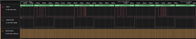
The error I am receiving is -11 that means timeout on read.
Kindly guide what could be at fault here.
Best.

