MPSL Assert Error and Arch_Except Reason 3 error when using BLE

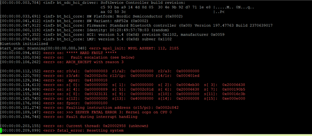
Hello, I have a custom board that was designed for me, but based off of the Acconeer XM126.  It is very similar with a few minor differences.  The person who designed it has bailed and is no longer reachable.  I am a mechanical engineer with limited coding and electrical knowledge.  I have had to stumble my way through.  There were multiple errors with the board that I have had to fix so far including the wrong HF crystal.  He originally had a 24mhz crystal and I had it replaced with a 32 and proper load capacitance.  The other issue is that he added a push button for BLE pairing.  It appears he meant to send 1.8v to pin y23 when the button is pushed.  It is incorrect and is sending 1.8v to y23 all the time.  I don't know if that could be an issue or not.  I'm not sure where the call out would be for what to do with that pin when it was getting the voltage.  I have searched his source and header files.  The board works with the radar sensor when I flash it with normal distance detecting programs.  However, when I load my program or any example program that uses BLE it gives me the errors I have attached.  MPSL Assert 112, 2185 and Arch except reason 3.  Also, zephyr fatal error 3: Kernel oops on cpu 0, fault during interrupt handling.  This is the last piece of the puzzle for me.  Does anyone have any idea what this might be?  Please remember I am limited in my knowledge.  I have already spent thousands to get here, so I am trying to solve this on my own.  Thanks.

Parents
  • Hi there Mike, 

    Can you share some more info here, its a bit difficult to get in to all the aspects whitout having an overview of the schematic. 

    But if the designers bailed and things have not been updated properly, but you have had to fix the physical board then things can be a bit difficult to debug. 


    The board works with the radar sensor when I flash it with normal distance detecting programs.  However, when I load my program or any example program that uses BLE it gives me the errors I have attached. 

    So looks like most of the HW is ok, but it would be good to see if only a basic sample with BLE would work. 

    Have you tested a simple application like Peripheral UART, https://github.com/nrfconnect/sdk-nrf/tree/main/samples/bluetooth/peripheral_uart.


    Also feel free to ask about anything and also know that we will help with review schematic and Hardware layout files.

    Regards,
    Jonathan

  • Hi Jonathan, thank you for the reply.  I will attach the schematic for you to review.  I also have the PCB files, if that matters.  In terms of trying samples, I have tried some from the Acconeer sdk and as long as it does not involve BLE they run fine.  Even the bring up example, which is basically a bunch of tests with the exception of BLE.  However, when I run any sample that tries to use a beacon/BLE I get the same error as with my program.  FYI, my program works on the XM126.  I have tried to go through the schematic the best I can and I don't see a lot of differences to the XM126 other than a charging circuit, push button, and some LED's. 

    However, he had put a resistor on the vset circuit of the vol reg and left it out.  It was supposed to go to ground for 1.8v.  So, I put a jumper there and it fixed that problem.  The HF crystal has been replaced, but maybe some solder crossed pads? Or it's a bad crystal?  I did notice the circuit is opposite direction, but from what I read that doesn't matter with the crystal.  Other than that HW wise, there is just that button.  You'll see it on the schematic.  I hope this helps. Also, I will try that periph uart example. 

    MikePCB_XM126_v1.0A.PDF

  • If nothing more is showing, like this line:

    LOG_INF("HFCLK started successfully. Stat: 0x%08x", NRF_CLOCK->HFCLKSTAT);

    Then the XTAL is not working. Is there anyone who can verify that the crystal is mounted correctly?

    Best regards,

    Edvin

  • I have a friend who has been doing the soldering for me when replacing the crystals.  They appear to be mounted correctly.  The only thing I can think of for mounting is that the solder on a pad is crossing over and connecting to the solder on another pad.  He uses flux and a hot air rework station. 

    Does the "Enable HFXO" got -11 mean anything?  Is it possible I got a batch of bad crystals?  I can try it with new crystals again.  

    Mike

  • From what I can tell, this is printed from zephyr_samples\boards\nrf\clock_skew\src\main.c, and the -11 is coming from clock_control_on() which will call api_blocking_start() in clock_control_nrf.c.

    I am not able to tell where the -11 return value is coming from, though. Perhaps you can debug and see where in api_blocking_start() -11 is coming from?

    Best regards,

    Edvin

  • Hello again.  So, I have tried to debug and basically found that the negative number means it is not working.  I have tried 3 new crystals on 3 new boards and double checked the solder.  I am still having the same issue.  The boards originally came from the manufacturer with 24mhz external crystals, which I know isn't right.  However, would I still be getting the same results for the clock_skew example if those crystals were working properly, but the wrong freq?  Or would it say something different?  Is there anything else that could cause this that I am missing?  I have sent my schematic previously.  Can I provide any other information?  Thanks.

    Mike

  • Hi Mike, 

    Can you share your GERBER files for the layout. 

    The schematic looks ok, do you have the datasheet of the crystals that you have used? 

    Regards,
    Jonathan

Reply Children
Related