MPSL Assert Error and Arch_Except Reason 3 error when using BLE

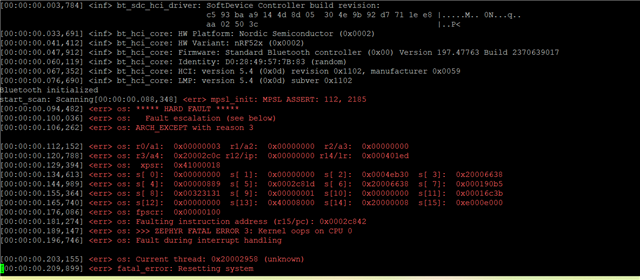
Hello, I have a custom board that was designed for me, but based off of the Acconeer XM126.  It is very similar with a few minor differences.  The person who designed it has bailed and is no longer reachable.  I am a mechanical engineer with limited coding and electrical knowledge.  I have had to stumble my way through.  There were multiple errors with the board that I have had to fix so far including the wrong HF crystal.  He originally had a 24mhz crystal and I had it replaced with a 32 and proper load capacitance.  The other issue is that he added a push button for BLE pairing.  It appears he meant to send 1.8v to pin y23 when the button is pushed.  It is incorrect and is sending 1.8v to y23 all the time.  I don't know if that could be an issue or not.  I'm not sure where the call out would be for what to do with that pin when it was getting the voltage.  I have searched his source and header files.  The board works with the radar sensor when I flash it with normal distance detecting programs.  However, when I load my program or any example program that uses BLE it gives me the errors I have attached.  MPSL Assert 112, 2185 and Arch except reason 3.  Also, zephyr fatal error 3: Kernel oops on cpu 0, fault during interrupt handling.  This is the last piece of the puzzle for me.  Does anyone have any idea what this might be?  Please remember I am limited in my knowledge.  I have already spent thousands to get here, so I am trying to solve this on my own.  Thanks.
Parents
  • Hi there Mike, 

    Can you share some more info here, its a bit difficult to get in to all the aspects whitout having an overview of the schematic. 

    But if the designers bailed and things have not been updated properly, but you have had to fix the physical board then things can be a bit difficult to debug. 


    The board works with the radar sensor when I flash it with normal distance detecting programs.  However, when I load my program or any example program that uses BLE it gives me the errors I have attached. 

    So looks like most of the HW is ok, but it would be good to see if only a basic sample with BLE would work. 

    Have you tested a simple application like Peripheral UART, https://github.com/nrfconnect/sdk-nrf/tree/main/samples/bluetooth/peripheral_uart.


    Also feel free to ask about anything and also know that we will help with review schematic and Hardware layout files.

    Regards,
    Jonathan

  • Hi Jonathan, thank you for the reply.  I will attach the schematic for you to review.  I also have the PCB files, if that matters.  In terms of trying samples, I have tried some from the Acconeer sdk and as long as it does not involve BLE they run fine.  Even the bring up example, which is basically a bunch of tests with the exception of BLE.  However, when I run any sample that tries to use a beacon/BLE I get the same error as with my program.  FYI, my program works on the XM126.  I have tried to go through the schematic the best I can and I don't see a lot of differences to the XM126 other than a charging circuit, push button, and some LED's. 

    However, he had put a resistor on the vset circuit of the vol reg and left it out.  It was supposed to go to ground for 1.8v.  So, I put a jumper there and it fixed that problem.  The HF crystal has been replaced, but maybe some solder crossed pads? Or it's a bad crystal?  I did notice the circuit is opposite direction, but from what I read that doesn't matter with the crystal.  Other than that HW wise, there is just that button.  You'll see it on the schematic.  I hope this helps. Also, I will try that periph uart example. 

    MikePCB_XM126_v1.0A.PDF

  • Hi Mike, 

    Can you share your GERBER files for the layout. 

    The schematic looks ok, do you have the datasheet of the crystals that you have used? 

    Regards,
    Jonathan

  • Project Outputs for PCB_XM126_v1.0A.zip

    Jonathan, here is the zip with the gerber files.  The link to the crystal is below.  I appreciate your help with this.

    https://support.epson.biz/td/api/doc_check.php?dl=brief_FA-20H&lang=en

    Mike

  • Hi Mike, 

    I don't see any issue in the design her other then the few things pointed to previously, crystal also should be ok. 

    Here is a file that you can test on your custom board:
    nrf52 carrier ch40 4dBm.hex

    It will just set the device in one mode, radio on, single channel TX unmodulated. Thats it, so if your device works this will show it. 

    You can use a DK and the nRF Connect for Desktop app RSSI Viewer to see if the device is pumping out any things on the radio. 

    Then we know that the HW at least partially works. 

    I will have another engineer have a look as well in case I missed something. 

    Regards,
    Jonathan

  • Jonathan,  Is there something specific I'm looking for?  When I run the app using the 52840 dk I get bars on every channel.  Do I just need to take it away from all other BLE sources?  I just used the programmer and the dk to flash the hex file to my board.  I run a a 2x5 socket cable from the dk to my boot board.  Then just power my board by usb and the have the dk plugged into my computer.  How would I know if it is picking up my boards signal?

    Mike

  • Hi Mike, 

    You should see a clear spike on the channel it is outputting at. 

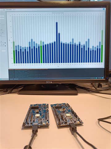
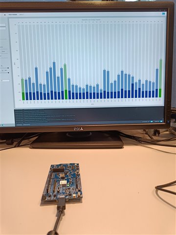
    Here is an example where one device is running the same hex and the other is RSSI viewer, as you can see there is a spike in the middle here, that is what we are looking for. 


    This is only the RSSI viewer in an office environment with a lot of other BLE devices. 


    So hopefully you see something close to the first image here with the spike in the middle around 2440 MHz.

    Regards,
    Jonathan

Reply
  • Hi Mike, 

    You should see a clear spike on the channel it is outputting at. 

    Here is an example where one device is running the same hex and the other is RSSI viewer, as you can see there is a spike in the middle here, that is what we are looking for. 


    This is only the RSSI viewer in an office environment with a lot of other BLE devices. 


    So hopefully you see something close to the first image here with the spike in the middle around 2440 MHz.

    Regards,
    Jonathan

Children
No Data
Related