Programming a custom external board using nRF52832 dk

Hello, 

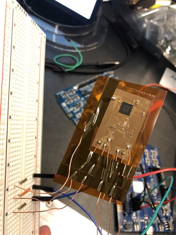
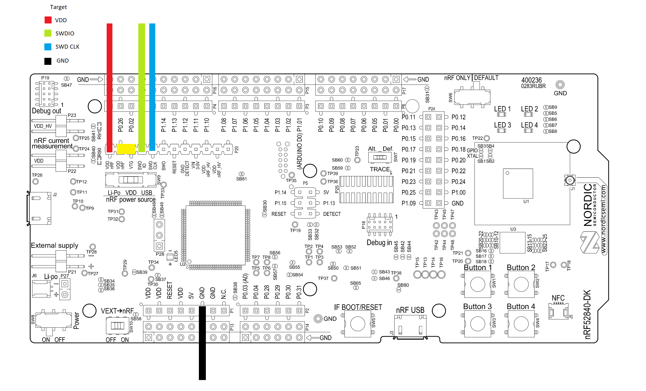
For my project I am making a custom circuit board which is pretty much just the nRF52832 chip and the surrounding capacitors and whatnot. I'd like to program this circuit board using my nRFdk, but am unsure how to do it. I actually have two of the dk circuit boards, and I was trying to use one to program the other to test the process before trying it on my custom circuit board. However, I was running into some issues.

I suppose my question is this: How can I program my custom board using the development kit I already have?

I've seen other posts where people were able to program and external board using a dk, but many of these weren't resolved. Additionally, the ones that I saw were resolved seemed to have a key difference when compared to my situation, such as using the 9 pin connector debug in to program an external board (my custom board doesn't have this, only the connections directly to the nRF52832. Happy to provide more information, so let me know if that is needed. Additionally, if it isn't possible to program my custom board this way it would be good to know. 

Thank you!

Parents
  • Hi 

    Could you elaborate a bit regarding the "only the connections to the nRF52832"? 

    In general you need at least VDD, SWCK, SWDIO and GND to flash a board. You can read more about programming a board using custom connections for the nRF52832 here

    Regards

    Runar

  • By that I meant that effectively my custom board is just the nRF52832 chip, which I am trying to program using my development kit. On my custom board, I don't have the special 9 pin connector. I talked a little bit about my problem here and got some feedback which I was trying to clarify by making this post. I'll try the connections in the page you shared tomorrow.

    I suppose that the simplest version of the questions I have are:

    1. Can I program an external nRF52832 using the development kit I have (assuming I have access to all the pins on the external chip)?

    2. Is it possible to test this by programming another development kit, or is there no way to directly access the nRF52832 pins on the development kit?

    Thank you!

  • The issue is that I don't have the 10 pin cable, and I would consider getting it, but I don't plan on using it for my custom board, so there's no real point in using it to program the other dk (since this was just to test connections before programming my custom board). It sounds like there is no way to access the nRF52832 chip directly, meaning that I can't program the external dk unless I have the special cable.

    As far as programming the nRF52832 chip directly, would I just follow the schematic connections in the post that you shared with me?

    Thank you

  • connorshannon said:

    The issue is that I don't have the 10 pin cable, and I would consider getting it, but I don't plan on using it for my custom board, so there's no real point in using it to program the other dk (since this was just to test connections before programming my custom board). It sounds like there is no way to access the nRF52832 chip directly, meaning that I can't program the external dk unless I have the special cable.

    It might work if you use the p20 connect and connect as shown in figure 2 in the custom programming link. I can't guarantee anything but it's worth the try. My honest opinion would be to just get a 10 pin cable as the time spent trying to get the custom connection to work might easily surpass the cost of just getting a cable. 

    connorshannon said:

    As far as programming the nRF52832 chip directly, would I just follow the schematic connections in the post that you shared with me?

    That is correct just remember you need the gpio voltage on both devices

    Regards

    Runar

  • Okay, lets completely forget about programming my other dk. All I want to do is program a custom, external board, shown here 

    On this external board, which is mostly just the nRF52832 chip, I have access to Vdd, ground, swdio, and swdclk. My current connections are as follows:

    nRFDK     /    Custom          

    Gnd         -->   Gnd

    Vdd nrF   -->   Vdd

    SWDIO    -->   SWDIO

    SWDCLK -->   SWDCLK

    Also, I have connected Vdd to Vtg on the nrfdk debug out pins. The schematic should match the one shown here, which seemed to work for someone else.

    My custom board is not powered, and the dk I am using as a programmer is connected via the USBC to my laptop and is getting power through that. When I go to flash my code in VSCODE, I get the following error: 

    [error] [ Client] - Encountered error -102: Command read_device_info executed for 139 milliseconds with result -102
    [error] [ Worker] - An unknown error.
    [error] [ Client] - Encountered error -102: Command read_memory_descriptors executed for 28 milliseconds with result -102
    Failed to read device memories.

    I currently don't have access to the reset pin on my custom board, because I didn't think it was needed to program it. However, the image in this discussion post https://docs.nordicsemi.com/bundle/ug_nrf52832_dk/page/UG/dk/ext_programming_support_P20.html

    seems to show that the reset pin is required. 

    Is the schematic in the link the correct way to connect an external board and program it, or is my issue somewhere else? Any clarification would be greatly appreciated.

  • Have a look at my response to this post; not only does the VDD on both DK and custom board have to match (same voltage) but also the GND sense and VDD sense lines are required.

    programming-prototype-board-from-52-dk

    This is what I use on target boards using modules which have both the 10-way .05" pitch connector (same as P19) and a Tag-Connect 6-pin connector:

    10-Pin Cortex Debug Connector to 6-Pin TC2030 Footprint
    =======================================================
    1 VCC Sense   1   (must connect to a power source eg P20)
    3 GND         5
    5 GND         5
    7 NC / RTCK   -
    9 GND Detect  5
    2 SWDIO / TMS 2
    4 SWCLK / TCK 4
    6 SWO / TDO   6   (not required)
    8 NC / TDI    -
    10 nRESET     3   (not required)

    The target boards have the connection from the 10-way header as described above (all of them, no missing Gnd for example). I use a simple 10-way ribbon between nRF52DK P19 and the target board header.

    The 6-pin Tag-Connect is defined as this, which also works using the 6-pin to 20-pin J-TAG adapter board:

    1 VCC          (connect to a power source from nRF DK eg P20)
    2 SWDIO / TMS
    3 nRESET       (not required)
    4 SWCLK / TCK
    5 GND          (also connected to GNDDetect)
    6 SWO / TDO    (not required)

  • I'm not sure I understand. I do not plan on using a 10-way ribbon. Are the connections that I made wrong? I'm just looking for a clear explanation of what connections I need to make to program an external nRF52832 using my development kit, which I don't think is a particularly unique situation. However, I keep seeing many different ways depending on which post I look through.

Reply Children
  • Ok, ok - P20 it is. P20 was designed for a plug-in shield, which is why there is no physical GND on P20 (pin 8 is not GND). There are 2 lines missing from the photo posted earlier, SH_VTG and SH_GND_DETECT, pins 3 and 8. These 2 sense inputs (note not outputs) should be connected to the external board as otherwise if locally shorted to VDD and GND at the DK and the external board is removed the DK will be programmed for the code intended for the external board. Use of both SH_VTG and SH_GND_DETECT is black magic hidden from us users, but both are required for reliable operation. Supply of VDD and GND is fine as you have them already.

    20-pin P20:
    ===========
    1  VDD_nRF        DK 3V output to DUT (Connected to VDD by SB9)
    2  VDD            DK 3V output to DUT (Connected to VDD_nRF by SB9)
    3  SH_VTG         Input from DUT to detect shield VDD
    4  SH_SWDIO       SWDIO to DUT
    5  SH_SWCLK       SWCLK to DUT
    6  SH_SWO         (not required)
    7  SH_RESET       (not required)
    8  SH_GND_DETECT  Input from DUT to detect shield GND
    DUT= external board, aka Device Under Test

Related