Unable to Establish Connection to BC832 on NRF Connect After Programming via NRF52 DK

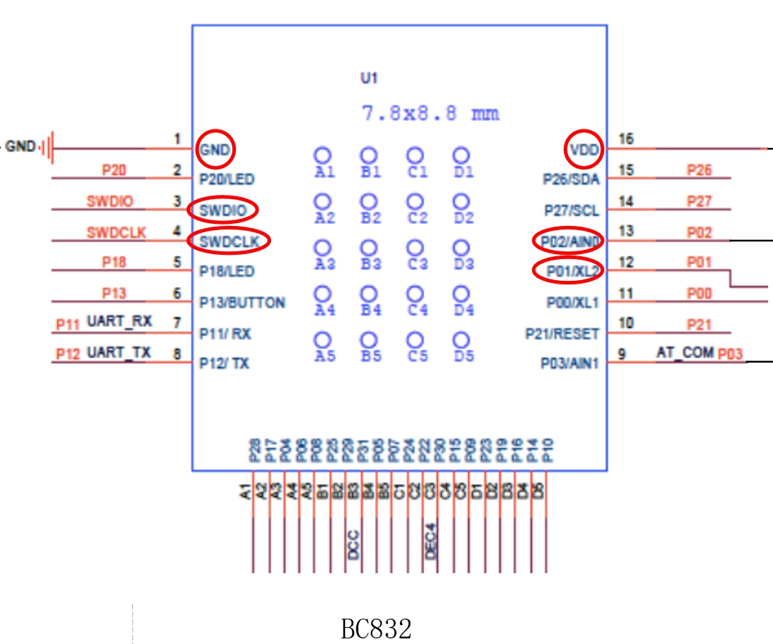
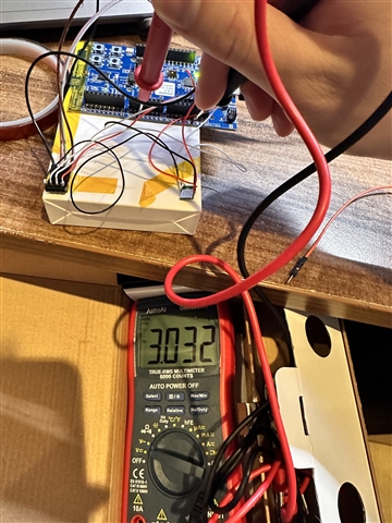
I am trying to program the BC832 (https://www.fanstel.com/bt832-1) using the NRF52DK (NRF52832). BC832 is a Bluetooth Low Energy (BLE) 5.3 with NFC module using Nordic nRF52832 SoC. A chip antenna is integrated. 

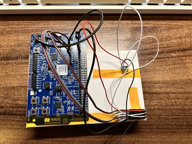
I followed the wiring instructions provided in this link: https://devzone.nordicsemi.com/f/nordic-q-a/55203/programming-external-board-bc832-with-nrf52840-dk.

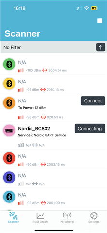
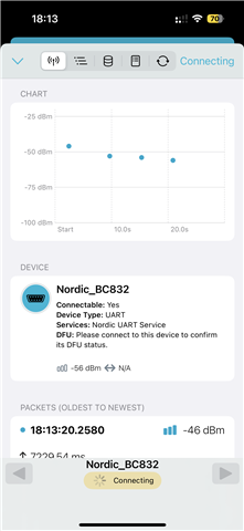
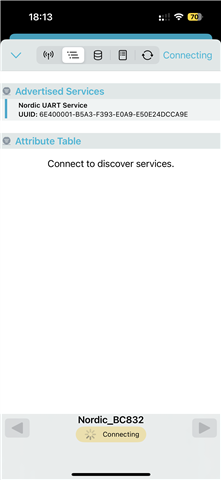
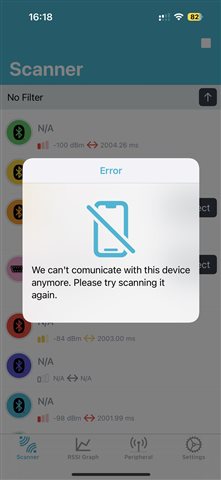
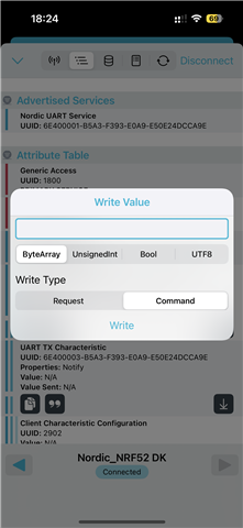
The result is that I can see the device name in NRF Connect, but it does not display signal strength (dBm) or connection latency (ms), and I am unable to connect to the device.

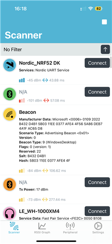
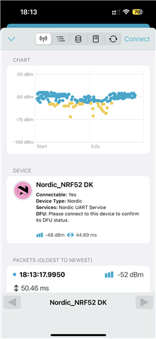
However, when I use the same code to program the NRF52DK, I can successfully connect to it in NRF Connect, see the signal strength and connection latency, and execute my intended commands.

I want to control the BC832 via my phone to achieve motor forward and reverse rotation by changing the GPIO pin's high and low levels. And here is my project file on SEGGER Embedded Studio, the path is "\ble_app_uart_bc832\pca10040\s132\ses"

ble_app_uart_bc832.zip

Could anyone kindly help me understand what might be causing the issue and suggest how I might resolve it? 

Thank you very much for your kind help!

Parents
  • Sloppy low-frequency clocks are fine for advertising but useless for a BLE connection. There is no 32kHz crystal fitted to this module (unless you added one) so these definitions (which assume LF crystal) are incorrect:

    //==========================================================
    
    // <h> Clock - SoftDevice clock configuration
    
    //==========================================================
    // <o> NRF_SDH_CLOCK_LF_SRC  - SoftDevice clock source.
     
    // <0=> NRF_CLOCK_LF_SRC_RC 
    // <1=> NRF_CLOCK_LF_SRC_XTAL 
    // <2=> NRF_CLOCK_LF_SRC_SYNTH 
    
    #ifndef NRF_SDH_CLOCK_LF_SRC
    #define NRF_SDH_CLOCK_LF_SRC 1
    #endif
    
    // <o> NRF_SDH_CLOCK_LF_RC_CTIV - SoftDevice calibration timer interval. 
    #ifndef NRF_SDH_CLOCK_LF_RC_CTIV
    #define NRF_SDH_CLOCK_LF_RC_CTIV 0
    #endif
    
    // <o> NRF_SDH_CLOCK_LF_RC_TEMP_CTIV - SoftDevice calibration timer interval under constant temperature. 
    // <i> How often (in number of calibration intervals) the RC oscillator shall be calibrated
    // <i>  if the temperature has not changed.
    
    #ifndef NRF_SDH_CLOCK_LF_RC_TEMP_CTIV
    #define NRF_SDH_CLOCK_LF_RC_TEMP_CTIV 0
    #endif
    
    // <o> NRF_SDH_CLOCK_LF_ACCURACY  - External clock accuracy used in the LL to compute timing.
     
    // <0=> NRF_CLOCK_LF_ACCURACY_250_PPM 
    // <1=> NRF_CLOCK_LF_ACCURACY_500_PPM 
    // <2=> NRF_CLOCK_LF_ACCURACY_150_PPM 
    // <3=> NRF_CLOCK_LF_ACCURACY_100_PPM 
    // <4=> NRF_CLOCK_LF_ACCURACY_75_PPM 
    // <5=> NRF_CLOCK_LF_ACCURACY_50_PPM 
    // <6=> NRF_CLOCK_LF_ACCURACY_30_PPM 
    // <7=> NRF_CLOCK_LF_ACCURACY_20_PPM 
    // <8=> NRF_CLOCK_LF_ACCURACY_10_PPM 
    // <9=> NRF_CLOCK_LF_ACCURACY_5_PPM 
    // <10=> NRF_CLOCK_LF_ACCURACY_2_PPM 
    // <11=> NRF_CLOCK_LF_ACCURACY_1_PPM 
    
    #ifndef NRF_SDH_CLOCK_LF_ACCURACY
    #define NRF_SDH_CLOCK_LF_ACCURACY 7
    #endif
    

    Rather than messing around trying to fix this I usually add the following at the top of sdk_config.h:

    #define NRFX_CLOCK_CONFIG_LF_SRC         0
    #define CLOCK_CONFIG_LF_SRC              0
    #define NRF_SDH_CLOCK_LF_SRC             0
    #define NRF_SDH_CLOCK_LF_RC_CTIV        16
    #define NRF_SDH_CLOCK_LF_RC_TEMP_CTIV    2
    #define NRF_SDH_CLOCK_LF_ACCURACY        1 // <1=> NRF_CLOCK_LF_ACCURACY_500_PPM
    

  • Thank you again for your previous help! I’ve successfully connected the BC832 module. However, I’ve encountered a new issue and was hoping you could offer some guidance.

    Currently, I am trying to send commands to change the voltage levels of pins 12 and 13 on the BC832. I used a multimeter to measure the voltage on these pins, and after sending the 01 and 02 commands, the measured voltage remains around 100mV. I am powering the BC832 via the VDD_nrf pin on the NRF52 DK, so theoretically, I expect the voltage on pins 12 and 13 to be around 3V when the corresponding commands are sent.

    To troubleshoot, I tried running the same code directly on the NRF52 DK, and I was able to change the voltage levels of pins 12 and 13 successfully using nRF Connect. The measured voltage was around 3V as expected.

    This leads me to believe the issue might be related to the code or its interaction with the BC832. Could you please offer any additional insights or advice on what might be causing this behavior?

    Thank you so much for your time and expertise!

Reply
  • Thank you again for your previous help! I’ve successfully connected the BC832 module. However, I’ve encountered a new issue and was hoping you could offer some guidance.

    Currently, I am trying to send commands to change the voltage levels of pins 12 and 13 on the BC832. I used a multimeter to measure the voltage on these pins, and after sending the 01 and 02 commands, the measured voltage remains around 100mV. I am powering the BC832 via the VDD_nrf pin on the NRF52 DK, so theoretically, I expect the voltage on pins 12 and 13 to be around 3V when the corresponding commands are sent.

    To troubleshoot, I tried running the same code directly on the NRF52 DK, and I was able to change the voltage levels of pins 12 and 13 successfully using nRF Connect. The measured voltage was around 3V as expected.

    This leads me to believe the issue might be related to the code or its interaction with the BC832. Could you please offer any additional insights or advice on what might be causing this behavior?

    Thank you so much for your time and expertise!

Children
  • Pin 12 (P0.01) may be set to the external crystal mode though pin 13 (P0.02) should work. One assumes you are using P0.01 and P0.02 and not P0.12 and P0.13?

    12 P01/XL2  C7 P0.01 GPIO, connection for 32.768kHz crystal
    13 P02/AIN0 C6 P0.02 GPIO, Analog input 0

    Should pin 13 work but not pin 12 try this, highly unlikely it would be required though:

       // Select 32kHz clock source to be internal RC
       //NRF_CLOCK->LFCLKSRC = CLOCK_LFCLKSRC_SRC_Xtal << CLOCK_LFCLKSRC_SRC_Pos;
         NRF_CLOCK->LFCLKSRC = CLOCK_LFCLKSRC_SRC_RC << CLOCK_LFCLKSRC_SRC_Pos;
       //NRF_CLOCK->LFCLKSRC = CLOCK_LFCLKSRC_SRC_Synth << CLOCK_LFCLKSRC_SRC_Pos;
    

  • Thank you so much for your suggestion about checking whether the pins are working properly. Using the following code:

    #include "nrf_gpio.h"
    #include "nrf_delay.h"
    
    #define TEST_PIN NRF_GPIO_PIN_MAP(0, 2) // P0.01
    //#define TEST_PIN NRF_GPIO_PIN_MAP(0, 2) // P0.02 
    
    int main(void)
    {
        NRF_CLOCK->TASKS_LFCLKSTOP = 1; 
        NRF_CLOCK->LFCLKSRC = CLOCK_LFCLKSRC_SRC_RC << CLOCK_LFCLKSRC_SRC_Pos; 
        NRF_CLOCK->TASKS_LFCLKSTART = 1; 
    
        nrf_gpio_cfg_default(TEST_PIN); 
        nrf_gpio_cfg_output(TEST_PIN); 
        // 
    
    
        while (1)
        {
            nrf_gpio_pin_set(TEST_PIN);   
            nrf_delay_ms(1000);         
            nrf_gpio_pin_clear(TEST_PIN); 
            nrf_delay_ms(1000);          
        }
    }
    

    I was able to test Pin 12 (P0.01) and Pin 13 (P0.02), and now I can detect voltage transitions. It seems that the issue was caused by not configuring the low-frequency clock properly and not resetting the pins to their default state. 

     BC832_V2.01_Dec-2017.pdfHere are the pin assignments and datasheet of BC832.

    After configuring Pin 12 (P0.01) and Pin 13 (P0.02) for GPIO functionality, I noticed that nRF Connect is unable to scan for BC832. I suspect this might be due to a conflict with BLE functionality, as Pin 12 (P0.01) is being used for GPIO instead of connecting to the external crystal oscillator required by BLE.

    To address this, I plan to use PIN 9 (P0.03) and Pin 12 (P0.01) for GPIO high/low transitions, keeping P0.01 available for BLE connectivity. However, even after making this change, I’m still unable to scan and detect BC832.

    Here is the project on SES now:ble_app_uart_bc832 - cannot scaned.zippath:"\ble_app_uart_bc832\pca10040\s132\ses"

    And here is the previous project where the BC832 could be detected, but pins 12 and 13 could not toggle voltage:ble_app_uart_bc832 - detected.zip

    Could this issue still be related to the crystal oscillator configuration, or am I missing something else critical? Thank you again for your time and expertise!

    Best regards,

    Steven

  • The LFCLK, crystal etc is handled for you when using BLE, so remove your code and instead rely on the correct configuration;

        // Initialize.
        uart_init();
        log_init();
        timers_init();
        buttons_leds_init(&erase_bonds);
        power_management_init();
        ble_stack_init();      // <<== this function initialises LFCLK for you
        ...
    

    For the BC832 which does not have a 32.768kHz low frequency crystal, place the following lines at the top of sdk_config.h:

    #define NRFX_CLOCK_CONFIG_LF_SRC         0
    #define CLOCK_CONFIG_LF_SRC              0
    #define NRF_SDH_CLOCK_LF_SRC             0
    #define NRF_SDH_CLOCK_LF_RC_CTIV        16
    #define NRF_SDH_CLOCK_LF_RC_TEMP_CTIV    2
    #define NRF_SDH_CLOCK_LF_ACCURACY        1 // <1=> NRF_CLOCK_LF_ACCURACY_500_PPM
    

    Do not write to LFCLK in your init_pins() as the SoftDevice handles that for you. Pin P0.01 is not used for BLE connectivity as there is no low frequency crystal.

    Nordic support team should step in here and propose nRFConnect SDK .. :-)

  • I sincerely want to thank you for your valuable guidance regarding the use of the nRF52 series and LFCLK initialization. Your clear and professional explanation has greatly helped me better understand how to manage this in my project. At the same time, I’d like to apologize if my frequent questions have caused any inconvenience or disruption. I truly appreciate your patience and generosity in taking the time to assist me.

    Thank you once again, and I wish you all the best!

Related