Problem identifying which GPIO is the cause for waking the MCU out of "system off" mode

Hi,

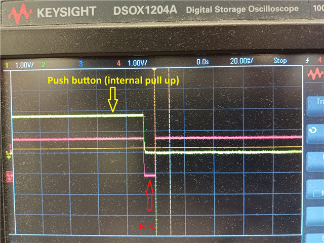
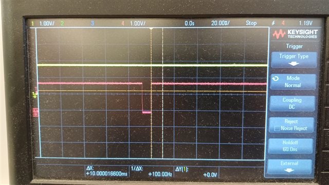
In my design, I have a push-button that pulls low when pressed and remains floating otherwise. This button is used to wake the nRF52832 from system off mode.

The push-button is connected to P0.11 which is configured as input with an internal pull-up. P0.11 is also configured to sense the input signal.

Additionally, I’m also using other GPIOs to wake the MCU from system off mode.

The issue I’m facing is as follows:

When a different GPIO (other than P0.11) wakes the MCU from system off mode and a reset occurs, the P0.11 pin is reset and no longer maintains its pull-up configuration. Instead, the signal is pulled low (though I’m not entirely sure why), which activates a latch even though the push-button wasn’t pressed.

I might have misunderstood the sequence of events.

Any help would be greatly appreciated.

Thanks!

Parents Reply Children
  • I would say so as well. I've not had to deal with that errata.

    The wonderful thing about the NRF52 series is there's always a workaround. Can you live with it for debug mode? Assuming not...

    Both pins are going to pull low but there'll be a slight timing difference which you can use.

    Complete hardware based solution...

    Wire both pins to GPIOTE.

    Then pass those events to two PPI's each wired into a separate PPI_GRP. Use the Fork on each PPI to disable the opposite group.

    Now also wire each PPI to the EGU using different event channels. Enable the interrupt.

    Now you'll get one interrupt and can look at the EGU events to know which pin actually fired.

    Reset the GPIO configs to deal with the errata, clear the PPI events and enable both PPI groups to start over.


Related