Hi guys,
I'm working on this project which was basically a migration from STM32 to the nordic NRF52832 in order to enable the BLE beaconing mode.
It has been a challenge to make all of the project to run on ZephyrsOS. However, the code is now at a state where all the previous functions are validated and working. I'm now missing the low power consumption mode. This is a battery powered project so the target consumption in idle state should be around 100uA.
Hardware details:
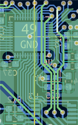
- Custom PCB
- LIS3DHTR accelerometer always powered
- EG915 Quectel with Mosfet for turning it off
- TDC1000 with Mosfet for turning it off
- MCP9700Ax-E/TO temperature sensor with Mosfet for turning it off
Requirements:
- Every 24H run the TDC1000 and MCP9700 and get a sample. Publish the sample using the EG915 and go back to sleep.
- Use LIS3DHTR to force a sample if high motion detected (interrupt pin), but this can wait.
I've read this article that explains the difference between system_off and system_on and for the NRF52832 I think I don't have other option than going with the system_on. System_off requires external pins to wake up (no timer based option) so it will not work for the 24H requirement. However, as a comparison I've tested the example system_off with my device_tree overlay:
nrf52dk_nrf52832.overlay
// To get started, press Ctrl+Space (or Option+Esc) to bring up the completion menu and view the available nodes.
// You can also use the buttons in the sidebar to perform actions on nodes.
// Actions currently available include:
// * Enabling / disabling the node
// * Adding the bus to a bus
// * Removing the node
// * Connecting ADC channels
// For more help, browse the DeviceTree documentation at https: //docs.zephyrproject.org/latest/guides/dts/index.html
// You can also visit the nRF DeviceTree extension documentation at https: //docs.nordicsemi.com/bundle/nrf-connect-vscode/page/guides/ncs_configure_app.html#devicetree-support-in-the-extension
/ {
aliases {
modem-uart = &uart0;
modem = &modem;
gasket-temp-sensor = &gasket_temp_sensor;
ambient-temp-sensor = &ambient_temp_sensor;
enable-level-sense = &enable_level_sense;
enable-modem-power = &enable_modem_power;
modem-pwr-key = &modem_pwr_key;
modem-rst-key = &modem_rst_key;
dbg-rx = &dbg_rx;
dbg-tx = &dbg_tx;
tdc1000-en = &tdc1000_en_pin;
tdc1000-rst = &tdc1000_rst_pin;
tdc1000-trigger = &tdc1000_trigger_pin;
tdc1000-chsel = &tdc1000_chsel_pin;
tdc1000-start = &tdc1000_start_pin;
tdc1000-stop = &tdc1000_stop_pin;
tdc1000-errb = &tdc1000_errb_pin;
};
gasket_temp_sensor: gasket_temp_sensor {
compatible = "microchip,mcp970x";
status = "okay";
family = "MCP9700/9700A";
io-channels = <&adc 0>;
friendly-name = "Gasket Temperature";
};
ambient_temp_sensor: ambient_temp_sensor {
compatible = "microchip,mcp970x";
status = "okay";
family = "MCP9700/9700A";
io-channels = <&adc 1>;
friendly-name = "Ambient Temperature";
};
zephyr,user {
io-channels = <&adc 2>;
io-channel-names = "battery_voltage";
};
enable_level_sense: enable_level_sense {
compatible = "power-switch";
gpios = <&gpio0 7 GPIO_ACTIVE_HIGH>;
};
enable_modem_power: enable_modem_power {
compatible = "power-switch";
gpios = <&gpio0 14 GPIO_ACTIVE_HIGH>;
};
modem_pwr_key: modem_pwr_key {
compatible = "power-switch";
gpios = <&gpio0 23 GPIO_ACTIVE_HIGH>;
};
modem_rst_key: modem_rst_key {
compatible = "power-switch";
gpios = <&gpio0 19 GPIO_ACTIVE_HIGH>;
};
tdc1000_en_pin: tdc1000_en_pin {
compatible = "power-switch";
gpios = <&gpio0 26 GPIO_ACTIVE_HIGH>;
};
tdc1000_rst_pin: tdc1000_rst_pin {
compatible = "power-switch";
gpios = <&gpio0 24 GPIO_ACTIVE_HIGH>;
};
tdc1000_trigger_pin: tdc1000_trigger_pin {
compatible = "power-switch";
gpios = <&gpio0 25 GPIO_ACTIVE_HIGH>;
};
tdc1000_chsel_pin: tdc1000_chsel_pin {
compatible = "power-switch";
gpios = <&gpio0 31 GPIO_ACTIVE_HIGH>;
};
tdc1000_start_pin: tdc1000_start_pin {
compatible = "input-switch";
gpios = <&gpio0 29 (GPIO_PULL_DOWN)>;
};
tdc1000_stop_pin: tdc1000_stop_pin {
compatible = "input-switch";
gpios = <&gpio0 28 (GPIO_PULL_DOWN)>;
};
tdc1000_errb_pin: tdc1000_errb_pin {
compatible = "input-switch";
gpios = <&gpio0 30 0>;
};
leds {
compatible = "gpio-leds";
dbg_rx: dbg_rx {
gpios = <&gpio0 6 GPIO_ACTIVE_LOW>;
};
dbg_tx: dbg_tx {
gpios = <&gpio0 8 GPIO_ACTIVE_HIGH>;
};
};
};
&gpio0 {
status = "okay";
};
&adc {
status = "okay";
#address-cells = <1>;
#size-cells = <0>;
channel@0 {
reg = <0>;
zephyr,gain = "ADC_GAIN_1_3";
zephyr,reference = "ADC_REF_INTERNAL";
zephyr,acquisition-time = <ADC_ACQ_TIME(ADC_ACQ_TIME_MICROSECONDS,10)>;
zephyr,input-positive = <NRF_SAADC_AIN0>;
zephyr,resolution = <12>; /* 0.055C per ADC step */
zephyr,oversampling = <2>; /* x4 */
};
channel@1 {
reg = <1>;
zephyr,gain = "ADC_GAIN_1_3";
zephyr,reference = "ADC_REF_INTERNAL";
zephyr,acquisition-time = <ADC_ACQ_TIME(ADC_ACQ_TIME_MICROSECONDS,10)>;
zephyr,input-positive = <NRF_SAADC_AIN1>;
zephyr,resolution = <12>; /* 0.055C per ADC step */
zephyr,oversampling = <2>; /* x4 */
};
channel@2 {
reg = <2>;
zephyr,gain = "ADC_GAIN_1_4";
zephyr,reference = "ADC_REF_VDD_1_4";
zephyr,acquisition-time = <ADC_ACQ_TIME_DEFAULT>;
zephyr,input-positive = <NRF_SAADC_AIN2>;
zephyr,resolution = <12>;
zephyr,oversampling = <2>; /* x4 */
zephyr,vref-mv = <825>;
};
};
&i2c0 {
status = "okay";
pinctrl-0 = <&i2c0_default>;
pinctrl-1 = <&i2c0_sleep>;
pinctrl-names = "default", "sleep";
lis3dh@19 {
compatible = "st,lis2dh";
reg = <0x19>;
irq-gpios = <&gpio0 5 GPIO_INT_WAKEUP>;
disconnect-sdo-sa0-pull-up;
};
};
&spi1 {
status = "okay";
cs-gpios = <&gpio0 18 GPIO_ACTIVE_LOW>;
pinctrl-0 = <&spi1_default>;
pinctrl-1 = <&spi1_sleep>;
pinctrl-names = "default", "sleep";
gendev: gendev@0 {
status = "okay";
compatible = "vnd,spi-device";
reg = <0>;
spi-max-frequency = <1600000>;
label = "GenDev";
};
};
&uart0 {
status = "okay";
pinctrl-0 = <&uart0_default>;
pinctrl-1 = <&uart0_sleep>;
pinctrl-names = "default", "sleep";
modem: modem {
status = "disabled";
compatible = "quectel,bg9x";
mdm-power-gpios = <&gpio0 23 0>;
mdm-reset-gpios = <&gpio0 19 0>;
};
};
&rtc0 {
status = "okay";
};
&pwm0 {
status = "okay";
pinctrl-0 = <&pwm0_default>;
pinctrl-1 = <&pwm0_sleep>;
pinctrl-names = "default", "sleep";
tdc_clk_in: tdc_clk_in {
status = "okay";
compatible = "pwm-clock";
#clock-cells = <1>;
pwms = <&pwm0 0 PWM_HZ(4000000) PWM_POLARITY_NORMAL>;
};
};
&pinctrl {
i2c0_default: i2c0_default {
group1 {
psels = <NRF_PSEL(TWIM_SCL, 0, 13)>, <NRF_PSEL(TWIM_SDA, 0, 12)>;
};
};
i2c0_sleep: i2c0_sleep {
group1 {
psels = <NRF_PSEL(TWIM_SCL, 0, 13)>, <NRF_PSEL(TWIM_SDA, 0, 12)>;
low-power-enable;
};
};
spi1_default: spi1_default {
group1 {
psels = <NRF_PSEL(SPIM_SCK, 0, 22)>,
<NRF_PSEL(SPIM_MOSI, 0, 20)>,
<NRF_PSEL(SPIM_MISO, 0, 17)>;
};
};
spi1_sleep: spi1_sleep {
group1 {
psels = <NRF_PSEL(SPIM_SCK, 0, 22)>,
<NRF_PSEL(SPIM_MOSI, 0, 20)>,
<NRF_PSEL(SPIM_MISO, 0, 17)>;
low-power-enable;
};
};
pwm0_default: pwm0_default {
group1 {
psels = <NRF_PSEL(PWM_OUT0, 0, 27)>; // TDC_CLK_8MHZ
};
};
pwm0_sleep: pwm0_sleep {
group1 {
psels = <NRF_PSEL(PWM_OUT0, 0, 27)>; // TDC_CLK_8MHZ
low-power-enable;
};
};
uart0_default: uart0_default {
group1 {
psels = <NRF_PSEL(UART_TX, 0, 16)>, <NRF_PSEL(UART_RX, 0, 15)>;
};
};
uart0_sleep: uart0_sleep {
group1 {
psels = <NRF_PSEL(UART_TX, 0, 16)>, <NRF_PSEL(UART_RX, 0, 15)>;
low-power-enable;
};
};
};
® {
regulator-initial-mode = <NRF5X_REG_MODE_LDO>;
};
// &gpiote0 {
// interrupts = <6 1>;
// };
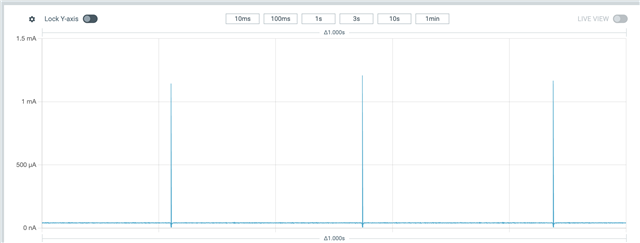
and I got a average consumption of around 40uA.
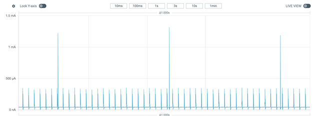
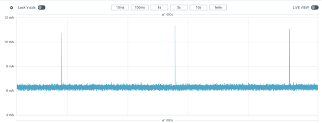
When I try the system_off in my project it doesn't work and the consumption is around 6mA.
nrf52kbd_nrf52832.overlay
// To get started, press Ctrl+Space (or Option+Esc) to bring up the completion menu and view the available nodes.
// You can also use the buttons in the sidebar to perform actions on nodes.
// Actions currently available include:
// * Enabling / disabling the node
// * Adding the bus to a bus
// * Removing the node
// * Connecting ADC channels
// For more help, browse the DeviceTree documentation at https: //docs.zephyrproject.org/latest/guides/dts/index.html
// You can also visit the nRF DeviceTree extension documentation at https: //docs.nordicsemi.com/bundle/nrf-connect-vscode/page/guides/ncs_configure_app.html#devicetree-support-in-the-extension
/ {
aliases {
modem-uart = &uart0;
modem = &modem;
gasket-temp-sensor = &gasket_temp_sensor;
ambient-temp-sensor = &ambient_temp_sensor;
enable-level-sense = &enable_level_sense;
enable-modem-power = &enable_modem_power;
modem-pwr-key = &modem_pwr_key;
modem-rst-key = &modem_rst_key;
dbg-rx = &dbg_rx;
dbg-tx = &dbg_tx;
tdc1000-en = &tdc1000_en_pin;
tdc1000-rst = &tdc1000_rst_pin;
tdc1000-trigger = &tdc1000_trigger_pin;
tdc1000-chsel = &tdc1000_chsel_pin;
tdc1000-start = &tdc1000_start_pin;
tdc1000-stop = &tdc1000_stop_pin;
tdc1000-errb = &tdc1000_errb_pin;
};
gasket_temp_sensor: gasket_temp_sensor {
compatible = "microchip,mcp970x";
status = "okay";
family = "MCP9700/9700A";
io-channels = <&adc 0>;
friendly-name = "Gasket Temperature";
};
ambient_temp_sensor: ambient_temp_sensor {
compatible = "microchip,mcp970x";
status = "okay";
family = "MCP9700/9700A";
io-channels = <&adc 1>;
friendly-name = "Ambient Temperature";
};
zephyr,user {
io-channels = <&adc 2>;
io-channel-names = "battery_voltage";
};
enable_level_sense: enable_level_sense {
compatible = "power-switch";
gpios = <&gpio0 7 GPIO_ACTIVE_HIGH>;
};
enable_modem_power: enable_modem_power {
compatible = "power-switch";
gpios = <&gpio0 14 GPIO_ACTIVE_HIGH>;
};
modem_pwr_key: modem_pwr_key {
compatible = "power-switch";
gpios = <&gpio0 23 GPIO_ACTIVE_HIGH>;
};
modem_rst_key: modem_rst_key {
compatible = "power-switch";
gpios = <&gpio0 19 GPIO_ACTIVE_HIGH>;
};
tdc1000_en_pin: tdc1000_en_pin {
compatible = "power-switch";
gpios = <&gpio0 26 GPIO_ACTIVE_HIGH>;
};
tdc1000_rst_pin: tdc1000_rst_pin {
compatible = "power-switch";
gpios = <&gpio0 24 GPIO_ACTIVE_HIGH>;
};
tdc1000_trigger_pin: tdc1000_trigger_pin {
compatible = "power-switch";
gpios = <&gpio0 25 GPIO_ACTIVE_HIGH>;
};
tdc1000_chsel_pin: tdc1000_chsel_pin {
compatible = "power-switch";
gpios = <&gpio0 31 GPIO_ACTIVE_HIGH>;
};
tdc1000_start_pin: tdc1000_start_pin {
compatible = "input-switch";
gpios = <&gpio0 29 (GPIO_PULL_DOWN)>;
};
tdc1000_stop_pin: tdc1000_stop_pin {
compatible = "input-switch";
gpios = <&gpio0 28 (GPIO_PULL_DOWN)>;
};
tdc1000_errb_pin: tdc1000_errb_pin {
compatible = "input-switch";
gpios = <&gpio0 30 0>;
};
leds {
compatible = "gpio-leds";
dbg_rx: dbg_rx {
gpios = <&gpio0 6 GPIO_ACTIVE_LOW>;
};
dbg_tx: dbg_tx {
gpios = <&gpio0 8 GPIO_ACTIVE_HIGH>;
};
};
};
&gpio0 {
status = "okay";
};
&adc {
status = "okay";
#address-cells = <1>;
#size-cells = <0>;
channel@0 {
reg = <0>;
zephyr,gain = "ADC_GAIN_1_3";
zephyr,reference = "ADC_REF_INTERNAL";
zephyr,acquisition-time = <ADC_ACQ_TIME(ADC_ACQ_TIME_MICROSECONDS,10)>;
zephyr,input-positive = <NRF_SAADC_AIN0>;
zephyr,resolution = <12>; /* 0.055C per ADC step */
zephyr,oversampling = <2>; /* x4 */
};
channel@1 {
reg = <1>;
zephyr,gain = "ADC_GAIN_1_3";
zephyr,reference = "ADC_REF_INTERNAL";
zephyr,acquisition-time = <ADC_ACQ_TIME(ADC_ACQ_TIME_MICROSECONDS,10)>;
zephyr,input-positive = <NRF_SAADC_AIN1>;
zephyr,resolution = <12>; /* 0.055C per ADC step */
zephyr,oversampling = <2>; /* x4 */
};
channel@2 {
reg = <2>;
zephyr,gain = "ADC_GAIN_1_4";
zephyr,reference = "ADC_REF_VDD_1_4";
zephyr,acquisition-time = <ADC_ACQ_TIME_DEFAULT>;
zephyr,input-positive = <NRF_SAADC_AIN2>;
zephyr,resolution = <12>;
zephyr,oversampling = <2>; /* x4 */
zephyr,vref-mv = <825>;
};
};
&i2c0 {
status = "okay";
pinctrl-0 = <&i2c0_default>;
pinctrl-1 = <&i2c0_sleep>;
pinctrl-names = "default", "sleep";
lis3dh@19 {
compatible = "st,lis2dh";
reg = <0x19>;
irq-gpios = <&gpio0 5 GPIO_INT_WAKEUP>;
disconnect-sdo-sa0-pull-up;
};
};
&spi1 {
status = "okay";
cs-gpios = <&gpio0 18 GPIO_ACTIVE_LOW>;
pinctrl-0 = <&spi1_default>;
pinctrl-1 = <&spi1_sleep>;
pinctrl-names = "default", "sleep";
gendev: gendev@0 {
status = "okay";
compatible = "vnd,spi-device";
reg = <0>;
spi-max-frequency = <1600000>;
label = "GenDev";
};
};
&uart0 {
status = "okay";
pinctrl-0 = <&uart0_default>;
pinctrl-1 = <&uart0_sleep>;
pinctrl-names = "default", "sleep";
modem: modem {
status = "disabled";
compatible = "quectel,bg9x";
mdm-power-gpios = <&gpio0 23 0>;
mdm-reset-gpios = <&gpio0 19 0>;
};
};
&rtc0 {
status = "okay";
};
&pwm0 {
status = "okay";
pinctrl-0 = <&pwm0_default>;
pinctrl-1 = <&pwm0_sleep>;
pinctrl-names = "default", "sleep";
tdc_clk_in: tdc_clk_in {
status = "okay";
compatible = "pwm-clock";
#clock-cells = <1>;
pwms = <&pwm0 0 PWM_HZ(4000000) PWM_POLARITY_NORMAL>;
};
};
&pinctrl {
i2c0_default: i2c0_default {
group1 {
psels = <NRF_PSEL(TWIM_SCL, 0, 13)>, <NRF_PSEL(TWIM_SDA, 0, 12)>;
};
};
i2c0_sleep: i2c0_sleep {
group1 {
psels = <NRF_PSEL(TWIM_SCL, 0, 13)>, <NRF_PSEL(TWIM_SDA, 0, 12)>;
low-power-enable;
};
};
spi1_default: spi1_default {
group1 {
psels = <NRF_PSEL(SPIM_SCK, 0, 22)>,
<NRF_PSEL(SPIM_MOSI, 0, 20)>,
<NRF_PSEL(SPIM_MISO, 0, 17)>;
};
};
spi1_sleep: spi1_sleep {
group1 {
psels = <NRF_PSEL(SPIM_SCK, 0, 22)>,
<NRF_PSEL(SPIM_MOSI, 0, 20)>,
<NRF_PSEL(SPIM_MISO, 0, 17)>;
low-power-enable;
};
};
pwm0_default: pwm0_default {
group1 {
psels = <NRF_PSEL(PWM_OUT0, 0, 27)>; // TDC_CLK_8MHZ
};
};
pwm0_sleep: pwm0_sleep {
group1 {
psels = <NRF_PSEL(PWM_OUT0, 0, 27)>; // TDC_CLK_8MHZ
low-power-enable;
};
};
uart0_default: uart0_default {
group1 {
psels = <NRF_PSEL(UART_TX, 0, 16)>, <NRF_PSEL(UART_RX, 0, 15)>;
};
};
uart0_sleep: uart0_sleep {
group1 {
psels = <NRF_PSEL(UART_TX, 0, 16)>, <NRF_PSEL(UART_RX, 0, 15)>;
low-power-enable;
};
};
};
® {
regulator-initial-mode = <NRF5X_REG_MODE_LDO>;
};
// &gpiote0 {
// interrupts = <6 1>;
// };
prj.conf
CONFIG_SENSOR=y
CONFIG_LIS2DH=y
CONFIG_I2C=y
CONFIG_GPIO=y

CONFIG_LOG=n
CONFIG_USE_SEGGER_RTT=n
CONFIG_CONSOLE=n
CONFIG_RTT_CONSOLE=n
CONFIG_UART_CONSOLE=n

CONFIG_SERIAL=y
CONFIG_UART_INTERRUPT_DRIVEN=y

CONFIG_ADC=y
CONFIG_MCP970X=y

CONFIG_BT=y
CONFIG_PWM=y
CONFIG_CLOCK_CONTROL=y
CONFIG_SPI=y

CONFIG_WDT_LOG_LEVEL_INF=n
CONFIG_WATCHDOG=n
CONFIG_WDT_DISABLE_AT_BOOT=n

CONFIG_REQUIRES_FLOAT_PRINTF=y
CONFIG_BT_DEVICE_NAME="Beacon"

CONFIG_MAIN_THREAD_PRIORITY=10

CONFIG_LIS2DH_TRIGGER_GLOBAL_THREAD=y
CONFIG_LIS2DH_ACCEL_RANGE_2G=y
CONFIG_LIS2DH_OPER_MODE_LOW_POWER=y
CONFIG_LIS2DH_ODR_1=y
CONFIG_LIS2DH_ODR_RUNTIME=y

CONFIG_NRFX_TIMER0=y
CONFIG_NRFX_PPI=y

CONFIG_PM_DEVICE=y
CONFIG_POWEROFF=y
main.c
#include <stdio.h>
#include <stdbool.h>
#include <stdlib.h>
#include <zephyr/kernel.h>
#include <zephyr/drivers/gpio.h>
#include <zephyr/kernel.h>
#include <zephyr/usb/usb_device.h>
#include <zephyr/usb/usbd.h>
#include <zephyr/drivers/uart.h>
#include <zephyr/logging/log.h>
// #include <zephyr/drivers/watchdog.h>
#include <zephyr/pm/device.h>
#include <zephyr/sys/poweroff.h>
#include <zephyr/sys/util.h>

#include "accel_reader.h"
#include "tank_reader.h"
#include "cellular_handler.h"
#include "ble_handler.h"

/****************************************************** Asserts *******************************************************/

/****************************************************** Defines *******************************************************/
#define SLEEP_TIME_FOR_FLUSHING_MS 5000
// #define WDT_OPT 0
/****************************************************** Typedefs ******************************************************/

/***************************************************** Constants ******************************************************/
LOG_MODULE_REGISTER(main, LOG_LEVEL_INF);
const struct device *const sensor = DEVICE_DT_GET_ANY(st_lis2dh);

/***************************************************** Variables ******************************************************/

/*********************************************** Internal Declarations ************************************************/

/***************************************************** Functions ******************************************************/

int main(void)
{
    while (1)
    {
        int err;
        /* Power down the ACCEL reader device */
        err = pm_device_action_run(sensor, PM_DEVICE_ACTION_SUSPEND);
        if (err) {
            LOG_ERR("pm_device_action_run() failed (%d)\n", err);
        }

        sys_poweroff();
    }

    return 0;
}

/************************************************* Internal Functions *************************************************/
What could be the issue here? The only difference are the proj.conf files and the fact that in my project I'm using the nrf52kbd_nrf52832.overlay instead of the nrf52dk_nrf52832.overlay. Btw, I'm using the PPK2 to do the measurements.
Also, any suggestions/advices on how can I achieve the best low power performance?
Thank you for the ongoing support,
Best regards,
Fernando Fontes