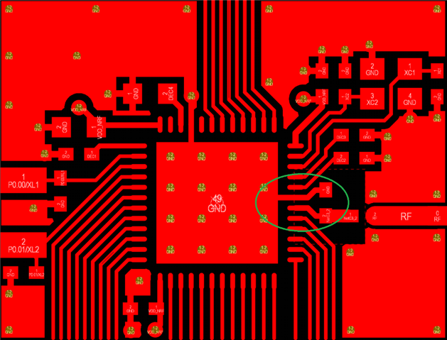
NRF52832 antena set-up

Hello,

I'm currently creating my own custom board for NRF 52832.

I put everything together, but I can't detect my custom board through Bluetooth using the NRF connect app. 

I'm using QFAA and QFAB QFN48 with DC/DC regulator setup.

Here I've attached the schematic of my custom board and all the components.

I'm new to designing an antenna for BLE. I believe there's something wrong with the antenna design. 

Please let me know if there's anything wrong with this design. 

Thank you!

Custom_nrf52832chip.pdf


Parents
  • Hi, 

    Can you share the layout files? GERBER format or PDF maybe?

    If you are able to program and read\write to the device then something is working at least. 


    We also have guides: https://devzone.nordicsemi.com/guides/hardware-design-test-and-measuring/b/nrf5x/posts/general-pcb-design-guidelines-for-nrf52-series 
    And a video made with one of our engineers: 

    PCB Antenna - How To Design, Measure And Tune 


    Also we will help with schematic and  layout review, all you need to to is submit a review request and share the schematic and layout files. 


    Feedback on the schematic you shared. 

    The antenna is missing its antenna matching network, so the antenna might not be tuned properly. 


    In the layout it should follow the ref design, and specifically the radio section should follow the ref layout as deviation form this layout can cause issues with suppression of harmonics. Tuning might be needed to achieve the best performance. 


    Also it is recommended to short two of the GPIO pins to ground, pin 37 and 38. 


    Regards,
    Jonathan

  • Hi Jonathan!

    Thank you so much for the reply.

    I'm not sure what you mean by layout file. I'm creating my CAD file using Rhino 7 software.

    I have attached a pdf file for the schematic:NRF52832_cad_final_Design.pdf

    Also, I used the AppCad program to calculate the dimension that is required for the antenna.

    This is the result that I got: 

    My PCB will be made out of 9-micron copper laminated on 25 microns Polyimide laminate.

    Also, what is the reasoning for connecting GPIO pins(37 and 38) to the ground pin??

    Please let me know what you think!


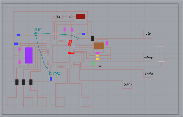
  • You need to add VDD on these sections. 

    Can be good to also have the red marked areas connected to ground. 

    But I recommend that you switch to KiCad or som other SW here to do the design, this will greatly help with the design process. There are also some relatively inexpensive PCB manufacturers like PCBway and JLCPCB that we have seen some customers use to make some designs.

    Regards,
    Jonathan

  • Thanks for the detailed posts, these were very helpful. We're going to look into a few of the things that you mentioned and get some more information. If things still aren't working after we try some other stuff, do you think there's any possibility we could quickly meet over zoom to discuss this? I'm not sure if that's something that is ever done for devzone posts, so if not no worries. Either way, we'll give what you mentioned a try and reach out once we've done so.

    Regards,

    Connor

  • Hi Connor, 

    connorshannon said:
    do you think there's any possibility we could quickly meet over zoom to discuss this?

    We dont do this. Only way to get this is through our sales department but that is not something that happens often.

    But I will happily answer any questions here and to my best to help you reach your goal here. 

    So feel free to keep asking here and I will do my best to help out. 


    I went digging though some of the other tickets here related and found an image in another ticket, looks like you are manufacturing your own pcb's here. Either machined out or with etching, this does work well and is relatively fast but can be difficult for more complex designes that involve radios. 

    I also did this some time ago and even with a design that was close to the reference design it did not yield great results as many of the PCB's did not preform well. I also hade to hand stich the top and bottom layer together with thin wire or lots of solder to make sure there was a consistent grund plane here, process is a lot more involved and there was room for more human error in my experience. 

    Regards,
    Jonathan

  • Hello Jonathan, 

    No worries, it makes sense that you don't do zoom meetings for devzone questions. I just wanted to update you: we changed the VDD connections, and since then everything has been working perfectly, including multiple different chips that we have manufactured that all are able to send data over bluetooth with no issues. It seems like the issue was indeed the VDD connections and not the antenna traces. Thank you for all the help, and I will reach out if anything new comes up.

  • Nice to see that you have success here with the design, what range do you get? 

    Regards,
    Jonathan

Reply Children
No Data
Related