SENT protocol based sensor configuration with nrf boards

hey there, i have a project which uses  nrf9151 with a pressures sensor from BOSCH which uses SENT protocol to transfer data, my question is

1. Is it possible to configure the SENT protocol on the nrf9151
2. if yes, how am i gonna configure what should i use?

Parents
  • The above is my implementation according to this

    SENT protocol driver using nRF Timer captures

    can someone please guide me where am i going wrong because i am unable to read any capture falling to falling edge period.

    thank you

  • I wrote some code to implement the algorithm I described, and it seems to work ok. I don't have a SENT sensor to hand, so I spoofed a test using just a Uart with 10 negative edges: {0xFF,0xB7,0xEF,0xBB, 0x7F} which decodes as SENT data A44FF4A4

    Algorithm:

    // Version using 4 peripheral Timers (most efficient) for nRF52 and nRF54:
    //
    //             |--------Fast Channel Data--------|       Optional
    // Sync  Stat    DN1   DN2   DN3   DN4   DN5   DN6   CRC    PAUSE       Description
    // ====  ===== ===== ===== ===== ===== ===== ===== ===== ========       ===========================
    //     +--------------------------------------------------------------  Edge  2: Sync
    //     |     +--------------------------------------------------------  Edge  3: Status
    //     |     |     +--------------------------------------------------  Edge  4: DN1
    //     |     |     |     +--------------------------------------------  Edge  5: DN2
    //     |     |     |     |     +--------------------------------------  Edge  6: DN3
    //     |     |     |     |     |     +--------------------------------  Edge  7: DN4
    //     |     |     |     |     |     |     +--------------------------  Edge  8: DN5
    //     |     |     |     |     |     |     |     +--------------------  Edge  9: DN6
    //     |     |     |     |     |     |     |     |     +--------------  Edge 10: CRC      Interrupt
    //     |     |     |     |     |     |     |     |     |        +-----  Edge 11: PAUSE (Optional)
    //     |     |     |     |     |     |     |     |     |        |
    // T4[0] T4[1] T4[2] T4[3] T4[4] T4[5] T1[0] T1[1] T1[2]    T1[3]  <== Timer Capture CC register Id
    //     ^     ^     ^     ^     ^     ^     ^     ^     ^        ^
    //     |     |     |     |     |     |     |     |     |        |  <== Counter compare triggers Timer capture
    //     |     |     |     |     |     |     |     |     |        |
    // C3[0] C3[1] C3[2] C3[3] C3[4] C3[5] C2[0] C2[1] C2[2]    C2[3]  <== Counter Compare CC register Id
    //     ^     ^     ^     ^     ^     ^     ^     ^     ^        ^
    //     |     |     |     |     |     |     |     |     |        |  <== Falling edge triggers counter increment
    //     |     |     |     |     |     |     |     |     |        |
    // ----+ +---+ +---+ +---+ +---+ +---+ +---+ +---+ +---+    +---+
    //     | ||||| ||||| ||||| ||||| ||||| ||||| ||||| |||||    |||||  <== Nibble Framing
    //     +-+   +-+   +-+   +-+   +-+   +-+   +-+   +-+   +----+   +-
    //     |     |     |     |     |     |     |     |     |        |
    //    56 12-27 12-27 12-27 12-27 12-27 12-27 12-27 12-27 (12-768)  <== SENT numer of Ticks range
    //     2     3     4     5     6     7     8     9    10     (11)  <== SENT Falling Edge Number
    // ====  ===== ===== ===== ===== ===== ===== ===== ===== ========
    // Sync  Stat    DN1   DN2   DN3   DN4   DN5   DN6   CRC    PAUSE
    //             |--------Fast Channel Data--------|       Optional
    
    //  Single Message
    //  {
    //    Counter EVENT      Timer Mode TASK     Nibble  Read registers
    //    =============      =================   ======  =================================
    //    Counter3-CC0  ==> capture Timer4-CC0   Sync
    //    Counter3-CC1  ==> capture Timer4-CC1   Status
    //    Counter3-CC2  ==> capture Timer4-CC2   DN1
    //    Counter3-CC3  ==> capture Timer4-CC3   DN2
    //    Counter3-CC4  ==> capture Timer4-CC4   DN3
    //    Counter3-CC5  ==> capture Timer4-CC5   DN4
    //    Counter2-CC0  ==> capture Timer1-CC0   DN5
    //    Counter2-CC1  ==> capture Timer1-CC1   DN6
    //    Counter2-CC2  ==> capture Timer1-CC2   CRC    Can start reading in interrupt here
    //    Counter2-CC3  ==> capture Timer1-CC3   PAUSE  read Timer4 CC0-CC5 and Timer1 CC0-CC3
    //  }

    Code - Proof of Concept; I used a few magic numbers as time is limited. Bare-metal but easy to translate to nRFx or (dare I say) nRFConnect:

    // PPI channels 0-19 are programmable, channels 20-31 are fixed
    #define PPI_SENT_SYNC      0 // Sync
    #define PPI_SENT_STATUS    1 // Status
    #define PPI_SENT_DN1       2 // DN1
    #define PPI_SENT_DN2       3 // DN2
    #define PPI_SENT_DN3       4 // DN3
    #define PPI_SENT_DN4       5 // DN4
    #define PPI_SENT_DN5       6 // DN5
    #define PPI_SENT_DN6       7 // DN6
    #define PPI_SENT_CRC       8 // CRC
    #define PPI_SENT_PAUSE     9 // PAUSE
    #define PPI_SENT_INPUT    10 // Input SENT signal
    #define PPI_SENT_TEST_HI  11 // Test output SENT signal high level
    #define PPI_SENT_TEST_LO  12 // Test output SENT signal low level
    #define PPI_SENT_START    13 // Use Input SENT signal to start timers
    
    // 8 GPIOTE channels available
    #define GPIOTE_SENT_INPUT 0 // Input SENT signal
    #define GPIOTE_SENT_TEST  1 // Test output SENT signal
    
    // Port pins to test SENT using PWM on output pin connected to SENT input pin
    #define PIN_SENT_INPUT    3 // Input SENT signal
    #define PIN_SENT_TEST     4 // Test output SENT signal, connect to Input SENT signal
    
    // TIMER0 is used by the RADIO, so don't use for now
    static NRF_TIMER_Type *pTimerSent_0to5   = NRF_TIMER4; // 6 x CC
    static NRF_TIMER_Type *pTimerSent_6to9   = NRF_TIMER1; // 4 x CC
    static NRF_TIMER_Type *pCounterSent_0to5 = NRF_TIMER3; // 6 x CC
    static NRF_TIMER_Type *pCounterSent_6to9 = NRF_TIMER2; // 4 x CC
    
    static void SentRxProtocol(void)
    {
       NRF_P0->OUTSET = (1 << PIN_SENT_INPUT);
       NRF_P0->OUTSET = (1 << PIN_SENT_TEST);
       // Configuration                       Direction    Input            Pullup         Drive Level      Sense Level
       // ================================    ==========   ==============   ============   ==============   =============
       NRF_P0->PIN_CNF[PIN_SENT_TEST]      = (PIN_OUTPUT | PIN_CONNECT    | PIN_PULLNONE | PIN_DRIVE_S0S1 | PIN_SENSE_OFF);
       NRF_P0->PIN_CNF[PIN_SENT_INPUT]     = (PIN_INPUT  | PIN_CONNECT    | PIN_PULLUP   | PIN_DRIVE_S0S1 | PIN_SENSE_LOW);
    
       // 32-bit timers
       pTimerSent_0to5->MODE    = TIMER_MODE_MODE_Timer;
       pTimerSent_0to5->BITMODE = TIMER_BITMODE_BITMODE_32Bit << TIMER_BITMODE_BITMODE_Pos;
       pTimerSent_6to9->MODE    = TIMER_MODE_MODE_Timer;
       pTimerSent_6to9->BITMODE = TIMER_BITMODE_BITMODE_32Bit << TIMER_BITMODE_BITMODE_Pos;
       // 1us timer period
       pTimerSent_0to5->PRESCALER = 0; // 16/2^4 -> 1MHz, 16/2^8->62.5KHz or 16uSec tick
       pTimerSent_6to9->PRESCALER = 0; // 16/2^4 -> 1MHz, 16/2^8->62.5KHz or 16uSec tick
       // Now clear timer registers
       pTimerSent_0to5->TASKS_CLEAR = 1;
       pTimerSent_6to9->TASKS_CLEAR = 1;
    
       // 32-bit counters
       pCounterSent_0to5->MODE    = TIMER_MODE_MODE_Counter;
       pCounterSent_0to5->BITMODE = TIMER_BITMODE_BITMODE_32Bit << TIMER_BITMODE_BITMODE_Pos;
       pCounterSent_6to9->MODE    = TIMER_MODE_MODE_Counter;
       pCounterSent_6to9->BITMODE = TIMER_BITMODE_BITMODE_32Bit << TIMER_BITMODE_BITMODE_Pos;
       // Prescaler not used in counter mode
       pCounterSent_0to5->PRESCALER = 0;
       pCounterSent_6to9->PRESCALER = 0;
    
       // Configure input event for count on falling edge
       NRF_GPIOTE->CONFIG[GPIOTE_SENT_INPUT] = GPIOTE_CONFIG_MODE_Event      << GPIOTE_CONFIG_MODE_Pos     |
                                               GPIOTE_CONFIG_POLARITY_HiToLo << GPIOTE_CONFIG_POLARITY_Pos |
                                               PIN_SENT_INPUT                << GPIOTE_CONFIG_PSEL_Pos     |
                                               GPIOTE_CONFIG_OUTINIT_High    << GPIOTE_CONFIG_OUTINIT_Pos;
       // Configure test output task pin for use with PWM
       NRF_GPIOTE->CONFIG[GPIOTE_SENT_TEST]  = GPIOTE_CONFIG_MODE_Task       << GPIOTE_CONFIG_MODE_Pos     |
                                               GPIOTE_CONFIG_POLARITY_LoToHi << GPIOTE_CONFIG_POLARITY_Pos |
                                               PIN_SENT_TEST                 << GPIOTE_CONFIG_PSEL_Pos     |
                                               GPIOTE_CONFIG_OUTINIT_High    << GPIOTE_CONFIG_OUTINIT_Pos;
    
       // Count on falling edge of pulse via PPI
       NRF_PPI->CH[PPI_SENT_INPUT].EEP   = (uint32_t)&NRF_GPIOTE->EVENTS_IN[GPIOTE_SENT_INPUT];
       NRF_PPI->CH[PPI_SENT_INPUT].TEP   = (uint32_t)&pCounterSent_0to5->TASKS_COUNT;
       NRF_PPI->FORK[PPI_SENT_INPUT].TEP = (uint32_t)&pCounterSent_6to9->TASKS_COUNT;
       // Start timers on falling edge of pulse via PPI
       NRF_PPI->CH[PPI_SENT_START].EEP   = (uint32_t)&NRF_GPIOTE->EVENTS_IN[GPIOTE_SENT_INPUT];
       NRF_PPI->CH[PPI_SENT_START].TEP   = (uint32_t)&pTimerSent_0to5->TASKS_START;
       NRF_PPI->FORK[PPI_SENT_START].TEP = (uint32_t)&pTimerSent_6to9->TASKS_START;
    
       // Capture elapsed time on falling edge of compare count match via PPI
       for (uint32_t CC_Index=0, PPI_Index=PPI_SENT_SYNC; CC_Index<6; CC_Index++, PPI_Index++)
       {
          // Clear edge time compare events
          pTimerSent_0to5->CC[CC_Index] = 0;
          // Set compare edge count events
          pCounterSent_0to5->CC[CC_Index] = CC_Index+1;
          // Link edge event to time capture task
          NRF_PPI->CH[PPI_Index].EEP = (uint32_t)&pCounterSent_0to5->EVENTS_COMPARE[CC_Index];  // Event
          NRF_PPI->CH[PPI_Index].TEP = (uint32_t)&pTimerSent_0to5->TASKS_CAPTURE[CC_Index]; // Task
       }
    
       // Capture elapsed time on falling edge of compare count match via PPI
       for (uint32_t CC_Index=0, PPI_Index=PPI_SENT_SYNC; CC_Index<4; CC_Index++, PPI_Index++)
       {
          // Clear edge time compare events
          pTimerSent_6to9->CC[CC_Index] = 0;
          // Set compare edge count events
          pCounterSent_6to9->CC[CC_Index] = CC_Index+1+6;
          // Link edge event to time capture task
          NRF_PPI->CH[PPI_Index+6].EEP = (uint32_t)&pCounterSent_6to9->EVENTS_COMPARE[CC_Index];  // Event
          NRF_PPI->CH[PPI_Index+6].TEP = (uint32_t)&pTimerSent_6to9->TASKS_CAPTURE[CC_Index]; // Task
      }
    
       // Enable PPI channels
       NRF_GPIOTE->EVENTS_PORT = 0;
       NRF_PPI->CHENSET = (1UL << PPI_SENT_SYNC    ) |
                          (1UL << PPI_SENT_STATUS  ) |
                          (1UL << PPI_SENT_DN1     ) |
                          (1UL << PPI_SENT_DN2     ) |
                          (1UL << PPI_SENT_DN3     ) |
                          (1UL << PPI_SENT_DN4     ) |
                          (1UL << PPI_SENT_DN5     ) |
                          (1UL << PPI_SENT_DN6     ) |
                          (1UL << PPI_SENT_CRC     ) |
                          (1UL << PPI_SENT_PAUSE   ) |
                          (1UL << PPI_SENT_INPUT   ) |
                          (1UL << PPI_SENT_TEST_HI ) |
                          (1UL << PPI_SENT_TEST_LO ) |
                          (1UL << PPI_SENT_START);;
    
       // Now clear counter registers and start counters
       pCounterSent_0to5->TASKS_CLEAR = 1;
       pCounterSent_6to9->TASKS_CLEAR = 1;
       pCounterSent_0to5->TASKS_START = 1;
       pCounterSent_6to9->TASKS_START = 1;
       // Uart test data at 230400 baud
       uint8_t SentTestPacket[] = {0xFF,0xB7,0xEF,0xBB, 0x7F};
       //
       // 1              2    3  4      5     6        7   8   9     10       11     <== Falling edge number
       // !              !    !  |      !     !        !   !   !      !        !     <== Negative-going edges
       // |-----0x00-||  |-----0x24-||  |-----0x88-||  |-----0x23-||  |-----0x40-|   <== uart 8-bit data
       // 0 11111111 11  0 11101101 11  0 11110111 11  0 11011101 11  0 11111110 1   <== uart 10-bit data with start & stop, LSB first
       //               11    4  3      3     5        5   3   4      3        8     <== uart bit count between edges with start & stop
       //              691  276 207   207   345      345 207 276    207      552     <== Received counts between edges
       //               56   22  16    16    27       27  16  22     16       44     <== Ticks Synch=56, data-12 to 27
       //                     A   4     4     F        F   4   A      4              <== SENT decoded 8-bit data 0x0-0xF
       //                     |   |     |     |        |   |   |      |
       //                     |   |     |     |        |   |   |      +------------  CRC
       //                     |   |     |     |        |   |   +-------------------  DN5
       //                     |   |     |     |        |   +-----------------------  DN5
       //                     |   |     |     |        +---------------------------  DN4
       //                     |   |     |     +------------------------------------  DN3
       //                     |   |     +------------------------------------------  DN2
       //                     |   +------------------------------------------------  DN1
       //                     +----------------------------------------------------  STATUS
       // Decodes as SENT data A44FF4A4
       //
       uartSend(SentTestPacket, sizeof(SentTestPacket));
    
       // Sync is 56 Ticks, nibbles are between 12-27 Ticks
       const uint32_t SyncTicks = 56;
       uint32_t PulseWidth[10];
       uint32_t SyncWidth = pTimerSent_0to5->CC[0];
       PulseWidth[0] = pTimerSent_0to5->CC[0];
       PulseWidth[1] = pTimerSent_0to5->CC[1] - pTimerSent_0to5->CC[0];
       PulseWidth[2] = pTimerSent_0to5->CC[2] - pTimerSent_0to5->CC[1];
       PulseWidth[3] = pTimerSent_0to5->CC[3] - pTimerSent_0to5->CC[2];
       PulseWidth[4] = pTimerSent_0to5->CC[4] - pTimerSent_0to5->CC[3];
       PulseWidth[5] = pTimerSent_0to5->CC[5] - pTimerSent_0to5->CC[4];
       PulseWidth[6] = pTimerSent_6to9->CC[0] - pTimerSent_0to5->CC[5];
       PulseWidth[7] = pTimerSent_6to9->CC[1] - pTimerSent_6to9->CC[0];
       PulseWidth[8] = pTimerSent_6to9->CC[2] - pTimerSent_6to9->CC[1];
       PulseWidth[9] = pTimerSent_6to9->CC[3] - pTimerSent_6to9->CC[2];
    
       uint8_t Nibbles[9];
       Nibbles[0] = (uint8_t)(((PulseWidth[1] * SyncTicks)) / SyncWidth) - 12;
       Nibbles[1] = (uint8_t)(((PulseWidth[2] * SyncTicks)) / SyncWidth) - 12;
       Nibbles[2] = (uint8_t)(((PulseWidth[3] * SyncTicks)) / SyncWidth) - 12;
       Nibbles[3] = (uint8_t)(((PulseWidth[4] * SyncTicks)) / SyncWidth) - 12;
       Nibbles[4] = (uint8_t)(((PulseWidth[5] * SyncTicks)) / SyncWidth) - 12;
       Nibbles[5] = (uint8_t)(((PulseWidth[6] * SyncTicks)) / SyncWidth) - 12;
       Nibbles[6] = (uint8_t)(((PulseWidth[7] * SyncTicks)) / SyncWidth) - 12;
       Nibbles[7] = (uint8_t)(((PulseWidth[8] * SyncTicks)) / SyncWidth) - 12;
       Nibbles[8] = (uint8_t)(((PulseWidth[9] * SyncTicks)) / SyncWidth) - 12;
       // Errata: [78] TIMER: High current consumption when using timer STOP task only
       //  - Workaround: Use the SHUTDOWN task after the STOP task or instead of the STOP task
       //  - this also stops the Timer from hanging after a time change
       //  - affects nRF52832, nRF52840
       pCounterSent_0to5->TASKS_SHUTDOWN = 1;
       pCounterSent_6to9->TASKS_SHUTDOWN = 1;
       pTimerSent_0to5->TASKS_SHUTDOWN = 1;
       pTimerSent_6to9->TASKS_SHUTDOWN = 1;
       // There is no STOPPED Event, and this register is read-only, so add a delay to ensure it is stopped before changes
       __DSB();
       while(1)
       {
       }
    }

  • I wrote a 2-timer version, one timer counts SENT falling edges and the other counts time between the edges measured in 16MHz clock cycles. It works as well as the 4-timer version, tested with a UART to spoof the Bosch sensor.

    Algorithm:

    // Version using just 2 peripheral Timers for nRF52, nRF54 and nRF9151
    //
    //             |--------Fast Channel Data--------|       Optional
    // Sync  Stat    DN1   DN2   DN3   DN4   DN5   DN6   CRC    PAUSE  CC Description     Read Ts Set Cs
    // ====  ===== ===== ===== ===== ===== ===== ===== ===== ========  == =============== ======= ======
    //     +----------------------------------------------------------- 0 Edge  2: Sync
    //     |     +----------------------------------------------------- 1 Edge  3: Status
    //     |     |     +----------------------------------------------- 2 Edge  4: DN1
    //     |     |     |     +----------------------------------------- 3 Edge  5: DN2    0,1,2,3 0,1,2,3
    //     |     |     |     |     +----------------------------------- 4 Edge  6: DN3
    //     |     |     |     |     |     +----------------------------- 5 Edge  7: DN4    4,5
    //     |     |     |     |     |     |     +----------------------- 0 Edge  8: DN5
    //     |     |     |     |     |     |     |     +----------------- 1 Edge  9: DN6
    //     |     |     |     |     |     |     |     |     +----------- 2 Edge 10: CRC
    //     |     |     |     |     |     |     |     |     |        +-- 3 Edge 11: PAUSE  6,7,8,9
    //     |     |     |     |     |     |     |     |     |        |
    // T2[0] T2[1] T2[2] T2[3] T2[4] T2[5] T2[0] T2[1] T2[2]    T2[3]  <== Timer Capture CC register Id
    //     ^     ^     ^     ^     ^     ^     ^     ^     ^        ^
    //     |     |     |     |     |     |     |     |     |        |  <== Counter compare triggers Timer capture
    //     |     |     |     |     |     |     |     |     |        |
    // C3[0] C3[1] C3[2] C3[3] C3[4] C3[5] C3[0] C3[1] C3[2]    C3[3]  <== Counter Compare CC register Id
    //     ^     ^     ^     ^     ^     ^     ^     ^     ^        ^
    //     |     |     |     |     |     |     |     |     |        |  <== Falling edge triggers counter increment
    //     |     |     |     |     |     |     |     |     |        |
    // ----+ +---+ +---+ +---+ +---+ +---+ +---+ +---+ +---+    +---+
    //     | ||||| ||||| ||||| ||||| ||||| ||||| ||||| |||||    |||||  <== Nibble Framing
    //     +-+   +-+   +-+   +-+   +-+   +-+   +-+   +-+   +----+   +-
    //     |     |     |     |     |     |     |     |     |        |
    //    56 12-27 12-27 12-27 12-27 12-27 12-27 12-27 12-27 (12-768)  <== SENT numer of Ticks range
    //     2     3     4     5     6     7     8     9    10     (11)  <== SENT Falling Edge Number
    // ====  ===== ===== ===== ===== ===== ===== ===== ===== ========
    // Sync  Stat    DN1   DN2   DN3   DN4   DN5   DN6   CRC    PAUSE
    //             |--------Fast Channel Data--------|       Optional
    

    Code:

    // SENT protocol
    // SENT tick ranges from 3us to about 90us, with clock-rate tolerances as high as +-25%. Each
    // nibble begins with a 5us logic low followed by a variable-width logic-high pulse
    //
    // A SENT message frame includes a sync signal followed by eight nibbles and an optional pause,
    // the latter to make up fixed-length messages
    // A nibble ranges from 12 to 27 ticks (representing 0x0 to 0xF), optional Pause is 12-768 ticks
    
    // PPI channels 0-19 are programmable, channels 20-31 are fixed
    #define PPI_SENT_SYNC      0 // Sync
    #define PPI_SENT_STATUS    1 // Status
    #define PPI_SENT_DN1       2 // DN1
    #define PPI_SENT_DN2       3 // DN2
    #define PPI_SENT_DN3       4 // DN3
    #define PPI_SENT_DN4       5 // DN4
    #define PPI_SENT_DN5       6 // DN5
    #define PPI_SENT_DN6       7 // DN6
    #define PPI_SENT_CRC       8 // CRC
    #define PPI_SENT_PAUSE     9 // PAUSE
    #define PPI_SENT_INPUT    10 // Input SENT signal
    #define PPI_SENT_TEST_HI  11 // Test output SENT signal high level
    #define PPI_SENT_TEST_LO  12 // Test output SENT signal low level
    #define PPI_SENT_START    13 // Use Input SENT signal to start timers
    
    // 8 GPIOTE channels available
    #define GPIOTE_SENT_INPUT 0 // Input SENT signal
    #define GPIOTE_SENT_TEST  1 // Test output SENT signal
    
    // Port pins to test SENT using PWM on output pin connected to SENT input pin
    #define PIN_SENT_INPUT    3 // Input SENT signal
    #define PIN_SENT_TEST     4 // Test output SENT signal, connect to Input SENT signal
    
    // TIMER0 is used by the RADIO, so don't use for now
    #define SENT_TIMER_IRQn TIMER3_IRQn
    static NRF_TIMER_Type * const pTimerSent   = NRF_TIMER4; // 6 x CC
    static NRF_TIMER_Type * const pCounterSent = NRF_TIMER3; // 6 x CC
    // Sync is 56 Ticks, nibbles are between 12-27 Ticks
    static const uint32_t SyncTicks  = 56;
    static const uint32_t Data0Ticks = 12;
    static uint32_t PulseWidth[10];
    static volatile uint32_t PulseTimes[10];
    
    static void SentRxProtocolT2(void)
    {
       NRF_P0->OUTSET = (1 << PIN_SENT_INPUT);
       NRF_P0->OUTSET = (1 << PIN_SENT_TEST);
       // Configuration                       Direction    Input            Pullup         Drive Level      Sense Level
       // ================================    ==========   ==============   ============   ==============   =============
       NRF_P0->PIN_CNF[PIN_SENT_TEST]      = (PIN_OUTPUT | PIN_CONNECT    | PIN_PULLNONE | PIN_DRIVE_S0S1 | PIN_SENSE_OFF);
       NRF_P0->PIN_CNF[PIN_SENT_INPUT]     = (PIN_INPUT  | PIN_CONNECT    | PIN_PULLUP   | PIN_DRIVE_S0S1 | PIN_SENSE_LOW);
    
       // 32-bit timers
       pTimerSent->MODE    = TIMER_MODE_MODE_Timer;
       pTimerSent->BITMODE = TIMER_BITMODE_BITMODE_32Bit << TIMER_BITMODE_BITMODE_Pos;
       // 1us timer period
       pTimerSent->PRESCALER = 0; // 16MHz timer clock
       // Now clear timer registers
       pTimerSent->TASKS_CLEAR = 1;
    
       // 32-bit counters
       pCounterSent->MODE    = TIMER_MODE_MODE_Counter;
       pCounterSent->BITMODE = TIMER_BITMODE_BITMODE_32Bit << TIMER_BITMODE_BITMODE_Pos;
       // Prescaler not used in counter mode
       pCounterSent->PRESCALER = 0;
    
       // Enable IRQ on EVENTS_COMPARE[] 3 and 5
       pCounterSent->INTENSET = (TIMER_INTENSET_COMPARE3_Enabled << TIMER_INTENSET_COMPARE3_Pos) |
                                (TIMER_INTENSET_COMPARE5_Enabled << TIMER_INTENSET_COMPARE5_Pos);
    
       // Clear the counter when COMPARE5 event is triggered - doesn't work, so clear in interrupt
       //pCounterSent->SHORTS = (TIMER_SHORTS_COMPARE5_CLEAR_Enabled << TIMER_SHORTS_COMPARE5_CLEAR_Pos);
    
       // Set interrupt priority and enable interrupt
       NVIC_SetPriority(SENT_TIMER_IRQn, 6);
       NVIC_ClearPendingIRQ(SENT_TIMER_IRQn);
       //nrf_delay_us(100);
       NVIC_EnableIRQ(SENT_TIMER_IRQn);
    
       // Configure input event for count on falling edge
       NRF_GPIOTE->CONFIG[GPIOTE_SENT_INPUT] = GPIOTE_CONFIG_MODE_Event      << GPIOTE_CONFIG_MODE_Pos     |
                                               GPIOTE_CONFIG_POLARITY_HiToLo << GPIOTE_CONFIG_POLARITY_Pos |
                                               PIN_SENT_INPUT                << GPIOTE_CONFIG_PSEL_Pos     |
                                               GPIOTE_CONFIG_OUTINIT_High    << GPIOTE_CONFIG_OUTINIT_Pos;
       // Configure test output task pin for use with PWM
       NRF_GPIOTE->CONFIG[GPIOTE_SENT_TEST]  = GPIOTE_CONFIG_MODE_Task       << GPIOTE_CONFIG_MODE_Pos     |
                                               GPIOTE_CONFIG_POLARITY_LoToHi << GPIOTE_CONFIG_POLARITY_Pos |
                                               PIN_SENT_TEST                 << GPIOTE_CONFIG_PSEL_Pos     |
                                               GPIOTE_CONFIG_OUTINIT_High    << GPIOTE_CONFIG_OUTINIT_Pos;
    
       // Count on falling edge of pulse via PPI
       NRF_PPI->CH[PPI_SENT_INPUT].EEP   = (uint32_t)&NRF_GPIOTE->EVENTS_IN[GPIOTE_SENT_INPUT];
       NRF_PPI->CH[PPI_SENT_INPUT].TEP   = (uint32_t)&pCounterSent->TASKS_COUNT;
       // Start timers on falling edge of pulse via PPI
       NRF_PPI->CH[PPI_SENT_START].EEP   = (uint32_t)&NRF_GPIOTE->EVENTS_IN[GPIOTE_SENT_INPUT];
       NRF_PPI->CH[PPI_SENT_START].TEP   = (uint32_t)&pTimerSent->TASKS_START;
    
       // Capture elapsed time on falling edge of compare count match via PPI
       for (uint32_t CC_Index=0, PPI_Index=PPI_SENT_SYNC; CC_Index<6; CC_Index++, PPI_Index++)
       {
          // Clear edge time compare events
          pTimerSent->CC[CC_Index] = 0;
          // Set compare edge count events from 2 to 7
          pCounterSent->CC[CC_Index] = CC_Index+2;
          // Link edge event to time capture task
          NRF_PPI->CH[PPI_Index].EEP = (uint32_t)&pCounterSent->EVENTS_COMPARE[CC_Index]; // Event
          NRF_PPI->CH[PPI_Index].TEP = (uint32_t)&pTimerSent->TASKS_CAPTURE[CC_Index];    // Task
       }
    
       // Enable PPI channels
       NRF_GPIOTE->EVENTS_PORT = 0;
       NRF_PPI->CHENSET = (1UL << PPI_SENT_SYNC    ) | //  0
                          (1UL << PPI_SENT_STATUS  ) | //  1
                          (1UL << PPI_SENT_DN1     ) | //  2
                          (1UL << PPI_SENT_DN2     ) | //  3
                          (1UL << PPI_SENT_DN3     ) | //  4
                          (1UL << PPI_SENT_DN4     ) | //  5
                          (1UL << PPI_SENT_DN5     ) | //  6
                          (1UL << PPI_SENT_DN6     ) | //  7
                          (1UL << PPI_SENT_CRC     ) | //  8
                          (1UL << PPI_SENT_PAUSE   ) | //  9
                          (1UL << PPI_SENT_INPUT   ) | // 10
                          (1UL << PPI_SENT_TEST_HI ) | // 11
                          (1UL << PPI_SENT_TEST_LO ) | // 12
                          (1UL << PPI_SENT_START);;    // 13
    
       // Now clear counter registers and start counters
       pCounterSent->TASKS_CLEAR = 1;
       pCounterSent->TASKS_START = 1;
       // Uart test data at 230400 baud
       uint8_t SentTestPacket[] = {0xFF,0xB7,0xEF,0xBB, 0x7F};
       //
       // If single message, manually start counter before reception starts:
       //
       // 1              2    3  4      5     6        7   8   9     10       11     <== Falling edge number
       // 1              2    3  4      5     6        7   8   9     10       11     <== Falling edge count in pCounterSent
       // !              !    !  |      !     !        !   !   !      !        !     <== Negative-going edges
       // |-----0xFF-|   |-----0xB7-|   |-----0xEF-|   |-----0xBB-|   |-----0x7F-|   <== uart 8-bit data
       // 0 11111111 11  0 11101101 11  0 11110111 11  0 11011101 11  0 11111110 11  <== uart 10-bit data with start & stop, LSB first
       // |             11    4  3      3     5        5   3   4      3        8     <== uart bit count between edges with start & stop
       // |            691  276 207   207   345      345 207 276    207      552     <== Received 16MHz counts between edges
       // |             56   22  16    16    27       27  16  22     16       44     <== Ticks Synch=56, data-12 to 27
       // |            (2C)   A  4      4     F        F   4   A      4      (20)    <== SENT decoded 8-bit data 0x0-0xF
       // |              |    |  |      |     |        |   |   |      |        |
       // |              |    |  |      |     |        |   |   |      |        +---  PAUSE  Edge 11   Counter 11
       // |              |    |  |      |     |        |   |   |      +------------  CRC    Edge 10   Counter 10
       // |              |    |  |      |     |        |   |   +-------------------  DN5    Edge  9   Counter  9
       // |              |    |  |      |     |        |   +-----------------------  DN5    Edge  8   Counter  8
       // |              |    |  |      |     |        +---------------------------  DN4    Edge  7   Counter  7
       // |              |    |  |      |     +------------------------------------  DN3    Edge  6   Counter  6
       // |              |    |  |      +------------------------------------------  DN2    Edge  5   Counter  5
       // |              |    |  +-------------------------------------------------  DN1    Edge  4   Counter  4
       // |              |    +----------------------------------------------------  STATUS Edge  3   Counter  3
       // |              +---------------------------------------------------------  SYNC   Edge  2   Counter  2
       // +------------------------------------------------------------------------  START  Edge  1   Counter  1
       // Decodes as SENT data A44FF4A4
       //
       uartSend(SentTestPacket, sizeof(SentTestPacket));
    
       // Sync is 56 Ticks, nibbles are between 12-27 Ticks
       uint32_t SyncWidth = PulseTimes[0];
       PulseWidth[0] = PulseTimes[0];
       for (uint32_t i=1; i<sizeof(PulseTimes)/sizeof(PulseTimes[0]); i++)
       {
          PulseWidth[i] = PulseTimes[i] - PulseTimes[i-1];
       }
    
       // Calculate decoded SENT 4-bit nibbles
       uint8_t Nibbles[9];
       for (uint32_t i=0; i<sizeof(Nibbles)/sizeof(Nibbles[0]); i++)
       {
          Nibbles[i] = (uint8_t)(((PulseWidth[i+1] * SyncTicks)) / SyncWidth) - Data0Ticks;
       }
    
       // Stop before next repeat
       pCounterSent->TASKS_STOP = 1;
       pTimerSent->TASKS_STOP   = 1;
       __DSB();
    
       // Errata: [78] TIMER: High current consumption when using timer STOP task only
       //  - Workaround: Use the SHUTDOWN task after the STOP task or instead of the STOP task
       //  - this also stops the Timer from hanging after a time change
       //  - affects nRF52832, nRF52840
       pCounterSent->TASKS_SHUTDOWN = 1;
       pTimerSent->TASKS_SHUTDOWN   = 1;
       // There is no STOPPED Event, and this register is read-only, so add a delay to ensure it is stopped before changes
       __DSB();
       while(1)
       {
       }
    }
    
    // Counter CC0-3 will be used twice
    static volatile bool RepeatEdges = false;
    
    // This IRQ handler will trigger every 3rd and 5th SENT falling edge
    void TIMER3_IRQHandler(void)
    {
       // Every 3rd SENT negative-going edge
       if (pCounterSent->EVENTS_COMPARE[3] == 1)
       {
          pCounterSent->EVENTS_COMPARE[0] = 0;
          pCounterSent->EVENTS_COMPARE[1] = 0;
          pCounterSent->EVENTS_COMPARE[2] = 0;
          pCounterSent->EVENTS_COMPARE[3] = 0;
          if (!RepeatEdges)
          {
             RepeatEdges = true;
             PulseTimes[0] = pTimerSent->CC[0];
             PulseTimes[1] = pTimerSent->CC[1];
             PulseTimes[2] = pTimerSent->CC[2];
             PulseTimes[3] = pTimerSent->CC[3];
             // Set compare edge count events from 8 to 11
             pCounterSent->CC[0] =  8;
             pCounterSent->CC[1] =  9;
             pCounterSent->CC[2] = 10;
             pCounterSent->CC[3] = 11;
          }
          else
          {
             PulseTimes[6] = pTimerSent->CC[0];
             PulseTimes[7] = pTimerSent->CC[1];
             PulseTimes[8] = pTimerSent->CC[2];
             PulseTimes[9] = pTimerSent->CC[3];
          }
       }
       // Every 5th SENT negative-going edge
       if (pCounterSent->EVENTS_COMPARE[5] == 1)
       {
          pCounterSent->EVENTS_COMPARE[4] = 0;
          pCounterSent->EVENTS_COMPARE[5] = 0;
          PulseTimes[4] = pTimerSent->CC[4];
          PulseTimes[5] = pTimerSent->CC[5];
          // This works whereas SHORTS clear doesn't ..
          pCounterSent->TASKS_CLEAR;
       }
       __DSB();
    }

  • hi  

    I appreciate your time and effort in assisting me. Although I have successfully compiled the code by integrating it into a Blinky example, I am facing challenges in generating a SENT output signal on GPIO 4.

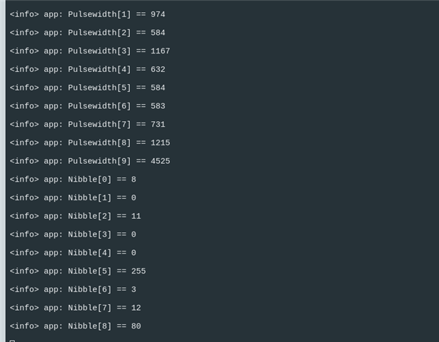
    The below is code which incorporate your function. i am getting these data which i am not sure if its correct, also i have connected the sensor on the GPIO 0.03.

    Can you please have a look and tell me where i am going wrong.

    NOTE: for initial testing i am using the nrf52840dk. with SENT pin connected on P0.03

    Looking forward to your guidance.

  • 
    #include <stdbool.h>
    #include <stdint.h>
    
    #include "nrf.h"
    #include "nordic_common.h"
    #include "boards.h"
    #include "nrf_delay.h"
    #include "nrf_log.h"
    #include "nrf_log_ctrl.h"
    #include "nrf_log_default_backends.h"
    
    
    // SENT protocol
    // SENT tick ranges from 3us to about 90us, with clock-rate tolerances as high as +-25%. Each
    // nibble begins with a 5us logic low followed by a variable-width logic-high pulse
    //
    // A SENT message frame includes a sync signal followed by eight nibbles and an optional pause,
    // the latter to make up fixed-length messages
    // A nibble ranges from 12 to 27 ticks (representing 0x0 to 0xF), optional Pause is 12-768 ticks
    
    // PPI channels 0-19 are programmable, channels 20-31 are fixed
    #define PPI_SENT_SYNC      0 // Sync
    #define PPI_SENT_STATUS    1 // Status
    #define PPI_SENT_DN1       2 // DN1
    #define PPI_SENT_DN2       3 // DN2
    #define PPI_SENT_DN3       4 // DN3
    #define PPI_SENT_DN4       5 // DN4
    #define PPI_SENT_DN5       6 // DN5
    #define PPI_SENT_DN6       7 // DN6
    #define PPI_SENT_CRC       8 // CRC
    #define PPI_SENT_PAUSE     9 // PAUSE
    #define PPI_SENT_INPUT    10 // Input SENT signal
    #define PPI_SENT_TEST_HI  11 // Test output SENT signal high level
    #define PPI_SENT_TEST_LO  12 // Test output SENT signal low level
    #define PPI_SENT_START    13 // Use Input SENT signal to start timers
    
    // 8 GPIOTE channels available
    #define GPIOTE_SENT_INPUT 0 // Input SENT signal
    #define GPIOTE_SENT_TEST  1 // Test output SENT signal
    
    // Port pins to test SENT using PWM on output pin connected to SENT input pin
    #define PIN_SENT_INPUT    3 // Input SENT signal
    #define PIN_SENT_TEST     4 // Test output SENT signal, connect to Input SENT signal
    
    // TIMER0 is used by the RADIO, so don't use for now
    #define SENT_TIMER_IRQn TIMER3_IRQn
    static NRF_TIMER_Type * const pTimerSent   = NRF_TIMER4; // 6 x CC
    static NRF_TIMER_Type * const pCounterSent = NRF_TIMER3; // 6 x CC
    // Sync is 56 Ticks, nibbles are between 12-27 Ticks
    static const uint32_t SyncTicks  = 56;
    static const uint32_t Data0Ticks = 12;
    static uint32_t PulseWidth[10];
    static volatile uint32_t PulseTimes[10];
    
    static void SentRxProtocolT2(void)
    {
       NRF_P0->OUTSET = (1 << PIN_SENT_INPUT);
       NRF_P0->OUTSET = (1 << PIN_SENT_TEST);
       // Configuration                       Direction    Input            Pullup         Drive Level      Sense Level
       // ================================    ==========   ==============   ============   ==============   =============
       //NRF_P0->PIN_CNF[PIN_SENT_TEST]      = (PIN_OUTPUT | PIN_CONNECT    | PIN_PULLNONE | PIN_DRIVE_S0S1 | PIN_SENSE_OFF);
       //NRF_P0->PIN_CNF[PIN_SENT_INPUT]     = (PIN_INPUT  | PIN_CONNECT    | PIN_PULLUP   | PIN_DRIVE_S0S1 | PIN_SENSE_LOW);
    
    
        // Configuration for PIN_SENT_TEST (output)
        NRF_P0->PIN_CNF[PIN_SENT_TEST] = (GPIO_PIN_CNF_DIR_Output << GPIO_PIN_CNF_DIR_Pos) |
                                     (GPIO_PIN_CNF_INPUT_Connect << GPIO_PIN_CNF_INPUT_Pos) |
                                     (GPIO_PIN_CNF_PULL_Disabled << GPIO_PIN_CNF_PULL_Pos) |
                                     (GPIO_PIN_CNF_DRIVE_S0S1 << GPIO_PIN_CNF_DRIVE_Pos) |
                                     (GPIO_PIN_CNF_SENSE_Disabled << GPIO_PIN_CNF_SENSE_Pos);
    
        // Configuration for PIN_SENT_INPUT (input with pull-up)
        NRF_P0->PIN_CNF[PIN_SENT_INPUT] = (GPIO_PIN_CNF_DIR_Input << GPIO_PIN_CNF_DIR_Pos) |
                                      (GPIO_PIN_CNF_INPUT_Connect << GPIO_PIN_CNF_INPUT_Pos) |
                                      (GPIO_PIN_CNF_PULL_Pullup << GPIO_PIN_CNF_PULL_Pos) |
                                      (GPIO_PIN_CNF_DRIVE_S0S1 << GPIO_PIN_CNF_DRIVE_Pos) |
                                      (GPIO_PIN_CNF_SENSE_Low << GPIO_PIN_CNF_SENSE_Pos);
    
       // 32-bit timers
       pTimerSent->MODE    = TIMER_MODE_MODE_Timer;
       pTimerSent->BITMODE = TIMER_BITMODE_BITMODE_32Bit << TIMER_BITMODE_BITMODE_Pos;
       // 1us timer period
       pTimerSent->PRESCALER = 0; // 16MHz timer clock
       // Now clear timer registers
       pTimerSent->TASKS_CLEAR = 1;
    
       // 32-bit counters
       pCounterSent->MODE    = TIMER_MODE_MODE_Counter;
       pCounterSent->BITMODE = TIMER_BITMODE_BITMODE_32Bit << TIMER_BITMODE_BITMODE_Pos;
       // Prescaler not used in counter mode
       pCounterSent->PRESCALER = 0;
    
       // Enable IRQ on EVENTS_COMPARE[] 3 and 5
       pCounterSent->INTENSET = (TIMER_INTENSET_COMPARE3_Enabled << TIMER_INTENSET_COMPARE3_Pos) |
                                (TIMER_INTENSET_COMPARE5_Enabled << TIMER_INTENSET_COMPARE5_Pos);
    
       // Clear the counter when COMPARE5 event is triggered - doesn't work, so clear in interrupt
       //pCounterSent->SHORTS = (TIMER_SHORTS_COMPARE5_CLEAR_Enabled << TIMER_SHORTS_COMPARE5_CLEAR_Pos);
    
       // Set interrupt priority and enable interrupt
       NVIC_SetPriority(SENT_TIMER_IRQn, 6);
       NVIC_ClearPendingIRQ(SENT_TIMER_IRQn);
       //nrf_delay_us(100);
       NVIC_EnableIRQ(SENT_TIMER_IRQn);
    
       // Configure input event for count on falling edge
       NRF_GPIOTE->CONFIG[GPIOTE_SENT_INPUT] = GPIOTE_CONFIG_MODE_Event      << GPIOTE_CONFIG_MODE_Pos     |
                                               GPIOTE_CONFIG_POLARITY_HiToLo << GPIOTE_CONFIG_POLARITY_Pos |
                                               PIN_SENT_INPUT                << GPIOTE_CONFIG_PSEL_Pos     |
                                               GPIOTE_CONFIG_OUTINIT_High    << GPIOTE_CONFIG_OUTINIT_Pos;
       // Configure test output task pin for use with PWM
       NRF_GPIOTE->CONFIG[GPIOTE_SENT_TEST]  = GPIOTE_CONFIG_MODE_Task       << GPIOTE_CONFIG_MODE_Pos     |
                                               GPIOTE_CONFIG_POLARITY_LoToHi << GPIOTE_CONFIG_POLARITY_Pos |
                                               PIN_SENT_TEST                 << GPIOTE_CONFIG_PSEL_Pos     |
                                               GPIOTE_CONFIG_OUTINIT_High    << GPIOTE_CONFIG_OUTINIT_Pos;
    
       // Count on falling edge of pulse via PPI
       NRF_PPI->CH[PPI_SENT_INPUT].EEP   = (uint32_t)&NRF_GPIOTE->EVENTS_IN[GPIOTE_SENT_INPUT];
       NRF_PPI->CH[PPI_SENT_INPUT].TEP   = (uint32_t)&pCounterSent->TASKS_COUNT;
       // Start timers on falling edge of pulse via PPI
       NRF_PPI->CH[PPI_SENT_START].EEP   = (uint32_t)&NRF_GPIOTE->EVENTS_IN[GPIOTE_SENT_INPUT];
       NRF_PPI->CH[PPI_SENT_START].TEP   = (uint32_t)&pTimerSent->TASKS_START;
    
       // Capture elapsed time on falling edge of compare count match via PPI
       for (uint32_t CC_Index=0, PPI_Index=PPI_SENT_SYNC; CC_Index<6; CC_Index++, PPI_Index++)
       {
          // Clear edge time compare events
          pTimerSent->CC[CC_Index] = 0;
          // Set compare edge count events from 2 to 7
          pCounterSent->CC[CC_Index] = CC_Index+2;
          // Link edge event to time capture task
          NRF_PPI->CH[PPI_Index].EEP = (uint32_t)&pCounterSent->EVENTS_COMPARE[CC_Index]; // Event
          NRF_PPI->CH[PPI_Index].TEP = (uint32_t)&pTimerSent->TASKS_CAPTURE[CC_Index];    // Task
       }
    
       // Enable PPI channels
       NRF_GPIOTE->EVENTS_PORT = 0;
       NRF_PPI->CHENSET = (1UL << PPI_SENT_SYNC    ) | //  0
                          (1UL << PPI_SENT_STATUS  ) | //  1
                          (1UL << PPI_SENT_DN1     ) | //  2
                          (1UL << PPI_SENT_DN2     ) | //  3
                          (1UL << PPI_SENT_DN3     ) | //  4
                          (1UL << PPI_SENT_DN4     ) | //  5
                          (1UL << PPI_SENT_DN5     ) | //  6
                          (1UL << PPI_SENT_DN6     ) | //  7
                          (1UL << PPI_SENT_CRC     ) | //  8
                          (1UL << PPI_SENT_PAUSE   ) | //  9
                          (1UL << PPI_SENT_INPUT   ) | // 10
                          (1UL << PPI_SENT_TEST_HI ) | // 11
                          (1UL << PPI_SENT_TEST_LO ) | // 12
                          (1UL << PPI_SENT_START);;    // 13
    
       // Now clear counter registers and start counters
       pCounterSent->TASKS_CLEAR = 1;
       pCounterSent->TASKS_START = 1;
       // Uart test data at 230400 baud
       uint8_t SentTestPacket[] = {0xFF,0xB7,0xEF,0xBB, 0x7F};
       //
       // 1              2    3  4      5     6        7   8   9     10       11     <== Falling edge number
       // !              !    !  |      !     !        !   !   !      !        !     <== Negative-going edges
       // |-----0xFF-||  |-----0xB7-||  |-----0xEF-||  |-----0xBB-||  |-----0x7F-|   <== uart 8-bit data
       // 0 11111111 11  0 11101101 11  0 11110111 11  0 11011101 11  0 11111110 1   <== uart 10-bit data with start & stop, LSB first
       // |             11    4  3      3     5        5   3   4      3        8     <== uart bit count between edges with start & stop
       // |            691  276 207   207   345      345 207 276    207      552     <== Received 16MHz counts between edges
       // |             56   22  16    16    27       27  16  22     16       44     <== Ticks Synch=56, data-12 to 27
       // |              |    A  4      4     F        F   4   A      4        |     <== SENT decoded 8-bit data 0x0-0xF
       // |              |    |  |      |     |        |   |   |      |        |
       // |              |    |  |      |     |        |   |   |      |        +---  PAUSE  Edge 11
       // |              |    |  |      |     |        |   |   |      +------------  CRC    Edge 10
       // |              |    |  |      |     |        |   |   +-------------------  DN5    Edge  9
       // |              |    |  |      |     |        |   +-----------------------  DN5    Edge  8
       // |              |    |  |      |     |        +---------------------------  DN4    Edge  7
       // |              |    |  |      |     +------------------------------------  DN3    Edge  6
       // |              |    |  |      +------------------------------------------  DN2    Edge  5
       // |              |    |  +-------------------------------------------------  DN1    Edge  4
       // |              |    +----------------------------------------------------  STATUS Edge  3
       // |              +---------------------------------------------------------  SYNC   Edge  2
       // +------------------------------------------------------------------------  START  Edge  1 (if already started)
       // Decodes as SENT data A44FF4A4
       //
       //uartSend(SentTestPacket, sizeof(SentTestPacket));
       NRF_LOG_INFO("hehe\n");
    
       // Sync is 56 Ticks, nibbles are between 12-27 Ticks
       uint32_t SyncWidth = PulseTimes[0];
       PulseWidth[0] = PulseTimes[0];
       for (uint32_t i=1; i<sizeof(PulseTimes)/sizeof(PulseTimes[0]); i++)
       {
          PulseWidth[i] = PulseTimes[i] - PulseTimes[i-1];
          NRF_LOG_INFO("Pulsewidth[%d] == %d\n", i, PulseWidth[i]);
       }
    
       // Calculate decoded SENT 4-bit nibbles
       uint8_t Nibbles[9];
       for (uint32_t i=0; i<sizeof(Nibbles)/sizeof(Nibbles[0]); i++)
       {
          Nibbles[i] = (uint8_t)(((PulseWidth[i+1] * SyncTicks)) / SyncWidth) - Data0Ticks;
          NRF_LOG_INFO("Nibble[%d] == %d\n", i, Nibbles[i]);
       }
    
       // Stop before next repeat
       pCounterSent->TASKS_STOP = 1;
       pTimerSent->TASKS_STOP   = 1;
       __DSB();
    
       // Errata: [78] TIMER: High current consumption when using timer STOP task only
       //  - Workaround: Use the SHUTDOWN task after the STOP task or instead of the STOP task
       //  - this also stops the Timer from hanging after a time change
       //  - affects nRF52832, nRF52840
       pCounterSent->TASKS_SHUTDOWN = 1;
       pTimerSent->TASKS_SHUTDOWN   = 1;
       // There is no STOPPED Event, and this register is read-only, so add a delay to ensure it is stopped before changes
       __DSB();
       while(1)
       {
       }
    }
    
    // Counter CC0-3 will be used twice
    static volatile bool RepeatEdges = false;
    
    // This IRQ handler will trigger every 3rd and 5th SENT falling edge
    void TIMER3_IRQHandler(void)
    {
       // Every 3rd SENT negative-going edge
       if (pCounterSent->EVENTS_COMPARE[3] == 1)
       {
          pCounterSent->EVENTS_COMPARE[0] = 0;
          pCounterSent->EVENTS_COMPARE[1] = 0;
          pCounterSent->EVENTS_COMPARE[2] = 0;
          pCounterSent->EVENTS_COMPARE[3] = 0;
          if (!RepeatEdges)
          {
             RepeatEdges = true;
             PulseTimes[0] = pTimerSent->CC[0];
             PulseTimes[1] = pTimerSent->CC[1];
             PulseTimes[2] = pTimerSent->CC[2];
             PulseTimes[3] = pTimerSent->CC[3];
             // Set compare edge count events from 8 to 11
             pCounterSent->CC[0] =  8;
             pCounterSent->CC[1] =  9;
             pCounterSent->CC[2] = 10;
             pCounterSent->CC[3] = 11;
          }
          else
          {
             PulseTimes[6] = pTimerSent->CC[0];
             PulseTimes[7] = pTimerSent->CC[1];
             PulseTimes[8] = pTimerSent->CC[2];
             PulseTimes[9] = pTimerSent->CC[3];
          }
       }
       // Every 5th SENT negative-going edge
       if (pCounterSent->EVENTS_COMPARE[5] == 1)
       {
          pCounterSent->EVENTS_COMPARE[4] = 0;
          pCounterSent->EVENTS_COMPARE[5] = 0;
          PulseTimes[4] = pTimerSent->CC[4];
          PulseTimes[5] = pTimerSent->CC[5];
          // This works whereas SHORTS clear doesn't ..
          pCounterSent->TASKS_CLEAR;
       }
       __DSB();
    }
    
    
    int main(void)
    {
        APP_ERROR_CHECK(NRF_LOG_INIT(NULL));
        NRF_LOG_DEFAULT_BACKENDS_INIT();
        NRF_LOG_INFO("hello\n\n");
        SentRxProtocolT2();
        while (true)
        {
          NRF_LOG_INFO("hello\n\n");  
          nrf_delay_ms(500);
        }
    }

  • Uncomment the UartSend() to send the expected SENT packet and use this function

    #define TX_PIN_NUMBER   PIN_SENT_TEST // SENT testing
    //#define TX_PIN_NUMBER   25       // PIN_FEATHER_TXD // P0.25
    #define RX_PIN_NUMBER   24       // PIN_FEATHER_RXD // P0.24
    
    void uartSend(const char * const Packet, const uint32_t PacketLength)
    {
       // Power on UART
       *(volatile uint32_t *)(NRF_UARTE0_BASE+0xFFC) = 1; //  UARTE Power Enable
       __DSB();
       if (!NRF_UARTE0->ENABLE)
       {
          nrf_gpio_pin_set(TX_PIN_NUMBER);
          // Configuration            Direction                Input                          Pullup               Drive Level        Sense Level
          // =====================    =======================  =============================  ===================  =================  =======================
          nrf_gpio_cfg(TX_PIN_NUMBER, NRF_GPIO_PIN_DIR_OUTPUT, NRF_GPIO_PIN_INPUT_DISCONNECT, NRF_GPIO_PIN_PULLUP, NRF_GPIO_PIN_H0H1, NRF_GPIO_PIN_NOSENSE);
          nrf_gpio_cfg(RX_PIN_NUMBER, NRF_GPIO_PIN_DIR_INPUT,  NRF_GPIO_PIN_INPUT_CONNECT,    NRF_GPIO_PIN_PULLUP, NRF_GPIO_PIN_H0H1, NRF_GPIO_PIN_NOSENSE);
          // Configure the UARTE with no flow control, no parity bit and 230400 baud rate
          NRF_UARTE0->CONFIG = (UART_CONFIG_HWFC_Disabled   << UART_CONFIG_HWFC_Pos) | (UART_CONFIG_PARITY_Excluded << UART_CONFIG_PARITY_Pos);
          NRF_UARTE0->BAUDRATE = UARTE_BAUDRATE_BAUDRATE_Baud230400 << UARTE_BAUDRATE_BAUDRATE_Pos;
          // Select TX and RX pins
          NRF_UARTE0->PSEL.TXD = TX_PIN_NUMBER;
          NRF_UARTE0->PSEL.RXD = RX_PIN_NUMBER;
          // Enable the UART (starts using the TX/RX pins)
          NRF_UARTE0->ENABLE = UARTE_ENABLE_ENABLE_Enabled << UARTE_ENABLE_ENABLE_Pos;
       }
       // Clear CTS which is always set on init regardless of HWFC
       NRF_UARTE0->EVENTS_CTS = 0;
       // Configure transmit buffer and start the transfer
       NRF_UARTE0->TXD.MAXCNT = PacketLength;
       NRF_UARTE0->TXD.PTR    = (uint32_t)Packet;
       NRF_UARTE0->TASKS_STARTTX = 1;
       // Wait until the transfer is complete
       while (NRF_UARTE0->EVENTS_ENDTX == 0)
       {
       }
       // Stop the UART TX
       NRF_UARTE0->TASKS_STOPTX = 1;
       __DSB();
       // Wait until we receive the stopped event
       while (NRF_UARTE0->EVENTS_TXSTOPPED == 0);
       NRF_UARTE0->EVENTS_ENDTX = 0;
       NRF_UARTE0->EVENTS_TXSTOPPED = 0;
       NRF_UARTE0->EVENTS_TXSTARTED = 0;
       // Disable the UARTE (pins are now available for other use)
       NRF_UARTE0->ENABLE = UARTE_ENABLE_ENABLE_Disabled << UARTE_ENABLE_ENABLE_Pos;
       __DSB();
       *(volatile uint32_t *)(NRF_UARTE0_BASE+0xFFC) = 0; //  UARTE Power Enable
    }

    Edit: I updated the single-message decode comments; I have a version which continually reads messages and checks them, which I'll post later (.. when I fix the issues with it ..).

      // If single message, manually start counter before reception starts:
      //
      // 1              2    3  4      5     6        7   8   9     10       11     <== Falling edge number
      // 1              2    3  4      5     6        7   8   9     10       11     <== Falling edge count in pCounterSent
      // !              !    !  |      !     !        !   !   !      !        !     <== Negative-going edges
      // |-----0xFF-|   |-----0xB7-|   |-----0xEF-|   |-----0xBB-|   |-----0x7F-|   <== uart 8-bit data
      // 0 11111111 11  0 11101101 11  0 11110111 11  0 11011101 11  0 11111110 11  <== uart 10-bit data with start & stop, LSB first
      // |             11    4  3      3     5        5   3   4      3        8     <== uart bit count between edges with start & stop
      // |            691  276 207   207   345      345 207 276    207      552     <== Received 16MHz counts between edges
      // |             56   22  16    16    27       27  16  22     16       44     <== Ticks Synch=56, data-12 to 27
      // |            (2C)   A  4      4     F        F   4   A      4      (20)    <== SENT decoded 8-bit data 0x0-0xF
      // |              |    |  |      |     |        |   |   |      |        |
      // |              |    |  |      |     |        |   |   |      |        +---  PAUSE  Edge 11   Counter 11
      // |              |    |  |      |     |        |   |   |      +------------  CRC    Edge 10   Counter 10
      // |              |    |  |      |     |        |   |   +-------------------  DN5    Edge  9   Counter  9
      // |              |    |  |      |     |        |   +-----------------------  DN5    Edge  8   Counter  8
      // |              |    |  |      |     |        +---------------------------  DN4    Edge  7   Counter  7
      // |              |    |  |      |     +------------------------------------  DN3    Edge  6   Counter  6
      // |              |    |  |      +------------------------------------------  DN2    Edge  5   Counter  5
      // |              |    |  +-------------------------------------------------  DN1    Edge  4   Counter  4
      // |              |    +----------------------------------------------------  STATUS Edge  3   Counter  3
      // |              +---------------------------------------------------------  SYNC   Edge  2   Counter  2
      // +------------------------------------------------------------------------  START  Edge  1   Counter  1
      // Decodes as SENT data A44FF4A4
    

  • hello  

    Thank your for replying, sorry to say i am confuse here as its my first time with bare metal, the thing is i have the sensor with me which i can connect to the nrf52840dk board so why i need the UART here?

    also i think there is some pin issue or other but i am unable to configure the uart, the program halt while configuring the UART.

    halt at this

    NRF_UARTE0->BAUDRATE = UARTE_BAUDRATE_BAUDRATE_Baud230400 << UARTE_BAUDRATE_BAUDRATE_Pos;

    Also can you please tell me which board are you using and also how have you made the connections if any?

    thanks and regards
    Akbar Shah

Reply
  • hello  

    Thank your for replying, sorry to say i am confuse here as its my first time with bare metal, the thing is i have the sensor with me which i can connect to the nrf52840dk board so why i need the UART here?

    also i think there is some pin issue or other but i am unable to configure the uart, the program halt while configuring the UART.

    halt at this

    NRF_UARTE0->BAUDRATE = UARTE_BAUDRATE_BAUDRATE_Baud230400 << UARTE_BAUDRATE_BAUDRATE_Pos;

    Also can you please tell me which board are you using and also how have you made the connections if any?

    thanks and regards
    Akbar Shah

Children
Related