SENT protocol based sensor configuration with nrf boards

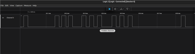
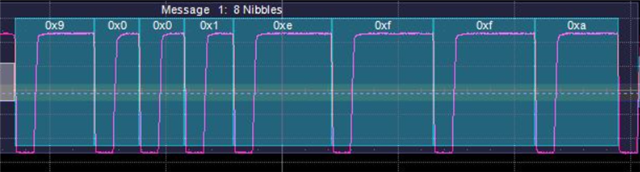
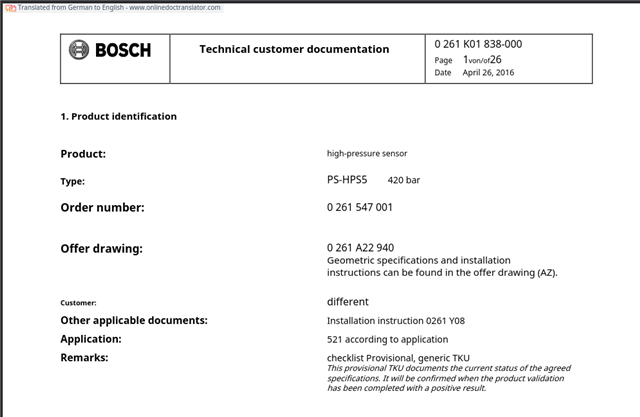
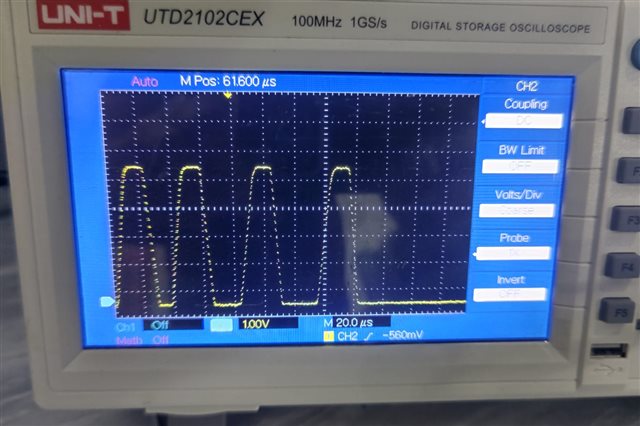
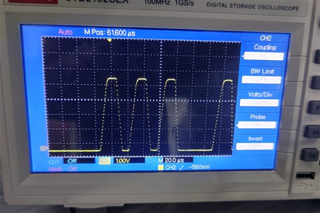
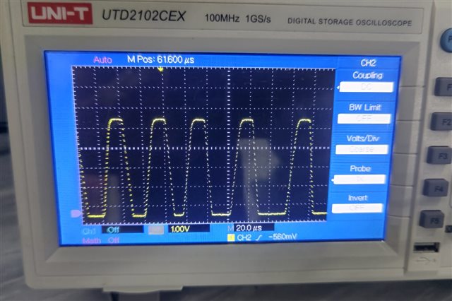
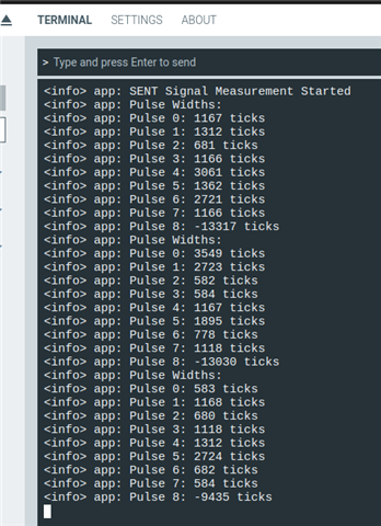
hey there, i have a project which uses  nrf9151 with a pressures sensor from BOSCH which uses SENT protocol to transfer data, my question is

1. Is it possible to configure the SENT protocol on the nrf9151
2. if yes, how am i gonna configure what should i use?

Parents
  • The above is my implementation according to this

    SENT protocol driver using nRF Timer captures

    can someone please guide me where am i going wrong because i am unable to read any capture falling to falling edge period.

    thank you

  • I wrote some code to implement the algorithm I described, and it seems to work ok. I don't have a SENT sensor to hand, so I spoofed a test using just a Uart with 10 negative edges: {0xFF,0xB7,0xEF,0xBB, 0x7F} which decodes as SENT data A44FF4A4

    Algorithm:

    Fullscreen
    1
    2
    3
    4
    5
    6
    7
    8
    9
    10
    11
    12
    13
    14
    15
    16
    17
    18
    19
    20
    21
    // Version using 4 peripheral Timers (most efficient) for nRF52 and nRF54:
    //
    // |--------Fast Channel Data--------| Optional
    // Sync Stat DN1 DN2 DN3 DN4 DN5 DN6 CRC PAUSE Description
    // ==== ===== ===== ===== ===== ===== ===== ===== ===== ======== ===========================
    // +-------------------------------------------------------------- Edge 2: Sync
    // | +-------------------------------------------------------- Edge 3: Status
    // | | +-------------------------------------------------- Edge 4: DN1
    // | | | +-------------------------------------------- Edge 5: DN2
    // | | | | +-------------------------------------- Edge 6: DN3
    // | | | | | +-------------------------------- Edge 7: DN4
    // | | | | | | +-------------------------- Edge 8: DN5
    // | | | | | | | +-------------------- Edge 9: DN6
    // | | | | | | | | +-------------- Edge 10: CRC Interrupt
    // | | | | | | | | | +----- Edge 11: PAUSE (Optional)
    // | | | | | | | | | |
    // T4[0] T4[1] T4[2] T4[3] T4[4] T4[5] T1[0] T1[1] T1[2] T1[3] <== Timer Capture CC register Id
    // ^ ^ ^ ^ ^ ^ ^ ^ ^ ^
    // | | | | | | | | | | <== Counter compare triggers Timer capture
    // | | | | | | | | | |
    // C3[0] C3[1] C3[2] C3[3] C3[4] C3[5] C2[0] C2[1] C2[2] C2[3] <== Counter Compare CC register Id
    XXXXXXXXXXXXXXXXXXXXXXXXXXXXXXXXXXXXXXXXXXXXXXXXXX

    Code - Proof of Concept; I used a few magic numbers as time is limited. Bare-metal but easy to translate to nRFx or (dare I say) nRFConnect:

    Fullscreen
    1
    2
    3
    4
    5
    6
    7
    8
    9
    10
    11
    12
    13
    14
    15
    16
    17
    18
    19
    20
    21
    // PPI channels 0-19 are programmable, channels 20-31 are fixed
    #define PPI_SENT_SYNC 0 // Sync
    #define PPI_SENT_STATUS 1 // Status
    #define PPI_SENT_DN1 2 // DN1
    #define PPI_SENT_DN2 3 // DN2
    #define PPI_SENT_DN3 4 // DN3
    #define PPI_SENT_DN4 5 // DN4
    #define PPI_SENT_DN5 6 // DN5
    #define PPI_SENT_DN6 7 // DN6
    #define PPI_SENT_CRC 8 // CRC
    #define PPI_SENT_PAUSE 9 // PAUSE
    #define PPI_SENT_INPUT 10 // Input SENT signal
    #define PPI_SENT_TEST_HI 11 // Test output SENT signal high level
    #define PPI_SENT_TEST_LO 12 // Test output SENT signal low level
    #define PPI_SENT_START 13 // Use Input SENT signal to start timers
    // 8 GPIOTE channels available
    #define GPIOTE_SENT_INPUT 0 // Input SENT signal
    #define GPIOTE_SENT_TEST 1 // Test output SENT signal
    // Port pins to test SENT using PWM on output pin connected to SENT input pin
    XXXXXXXXXXXXXXXXXXXXXXXXXXXXXXXXXXXXXXXXXXXXXXXXXX

  • resolved the UART issue it was due to logs were enabled, but i am still confuse how will i see the data now?

  • If testing with the sensor then don't use the UART; testing with the UART first ensures the code is working on the board in which vase connect P0.03 to P0.04 with the sensor removed.

    When that works remove the connection between P0.03 and P0.04 and reconnect the sensor to P0.03

    The code you are using only decodes a single message; does the sensor data look repeatable? Look at PulseTimes as well. It would be helpful to capture the sensor message on a scope so we can work out what the actual sensor packet contains.


  • this is the signal i captured using logic analyzer. the signal above is continuous. this is from the sensor.

  • Assuming the signal on the logic analyzer is sensor data, the signal looks like it is inverted; the level shifter you are using should be a buffer, not an inverter. Maybe try the resistor divider instead of the inverter; that should work.

  • i havnt used any level shifter between logic analyzer and the sensor, the SENT output is directly connected to the channel 0 of the logic analyzer.

Reply
  • i havnt used any level shifter between logic analyzer and the sensor, the SENT output is directly connected to the channel 0 of the logic analyzer.

Children
  • The signal looks inverted; which specific sensor are you using?

    From wikipedia:


  • this is the high pressure sensor from bosch, and also the SENT signal captured on oscilloscope. the signal is the same so i think if its inverted it should be done by the BOSCH.

  •   

    let say the signal is inverted then we can change the logic to capture rising to rising edge instead of falling to falling edge right?

    for you reference this is the datasheet of the sensor,

    0261 K01 838-000_HPS5_420bar_20160426.de.en.pdf

  • Yes the data can be inverted; try this:

    Fullscreen
    1
    2
    3
    4
    5
    6
    7
    8
    9
    10
    11
    12
    Falling edge:
    // Configure input event for count on falling edge
    NRF_GPIOTE->CONFIG[GPIOTE_SENT_INPUT] = GPIOTE_CONFIG_MODE_Event << GPIOTE_CONFIG_MODE_Pos |
    GPIOTE_CONFIG_POLARITY_HiToLo << GPIOTE_CONFIG_POLARITY_Pos |
    PIN_SENT_INPUT << GPIOTE_CONFIG_PSEL_Pos |
    GPIOTE_CONFIG_OUTINIT_High << GPIOTE_CONFIG_OUTINIT_Pos;
    Rising edge:
    // Configure input event for count on rising edge
    NRF_GPIOTE->CONFIG[GPIOTE_SENT_INPUT] = GPIOTE_CONFIG_MODE_Event << GPIOTE_CONFIG_MODE_Pos |
    GPIOTE_CONFIG_POLARITY_LoToHi << GPIOTE_CONFIG_POLARITY_Pos |
    PIN_SENT_INPUT << GPIOTE_CONFIG_PSEL_Pos |
    GPIOTE_CONFIG_OUTINIT_Low << GPIOTE_CONFIG_OUTINIT_Pos;
    XXXXXXXXXXXXXXXXXXXXXXXXXXXXXXXXXXXXXXXXXXXXXXXXXX

    Here's code for continuous reception of messages using only two timers. One timer counts SENT falling edges and the other counts time between the edges measured in 16MHz clock cycles.

    The algorithm:

    Fullscreen
    1
    2
    3
    4
    5
    6
    7
    8
    9
    10
    11
    12
    13
    14
    15
    16
    17
    18
    19
    20
    21
    // SENT protocol
    // SENT tick ranges from 3us to about 90us, with clock-rate tolerances as high as +-25%. Each
    // nibble begins with a 5us logic low followed by a variable-width logic-high pulse
    //
    // A SENT message frame includes a sync signal followed by eight nibbles and an optional pause,
    // the latter to make up fixed-length messages
    // A nibble ranges from 12 to 27 ticks (representing 0x0 to 0xF), optional Pause is 12-768 ticks
    //
    // |--------Fast Channel Data--------| Optional
    // Sync Status DN1 DN2 DN3 DN4 DN5 DN6 CRC PAUSE
    // ==== ====== ===== ===== ===== ===== ===== ===== ===== ========
    // 56 12-27 12-27 12-27 12-27 12-27 12-27 12-27 12-27 (12-768) <== SENT numer of Ticks range
    // 1 2 3 4 5 6 7 8 9 (10) <== SENT Falling Edge Number
    // C3[0] C3[1] C3[2] C3[3] C3[4] C3[5] C3[0] C3[1] C3[2] C3[3] <== Counter Compare CC register Id
    // T4[0] T4[1] T4[2] T4[3] T4[4] T4[5] T4[0] T4[1] T4[2] T4[3] <== Timer Capture CC register Id
    // Version using just 2 peripheral Timers for nRF52, nRF54 and nRF9151
    //
    // |---------Fast Channel Data--------| Optional
    // Sync Stat DN1 DN2 DN3 DN4 DN5 DN6 CRC PAUSE CC Edge CC Field Read Ts Set Cs
    // ==== ===== ===== ===== ===== ===== ===== ===== ===== ======== == ==== == ===== ======= ======
    XXXXXXXXXXXXXXXXXXXXXXXXXXXXXXXXXXXXXXXXXXXXXXXXXX

    Test messages using a hardware uart to spoof a SENT sensor:

    Fullscreen
    1
    2
    3
    4
    5
    6
    7
    8
    9
    10
    11
    12
    13
    14
    15
    16
    17
    18
    19
    20
    21
    // Uart test data at 230400 baud
    uint8_t SentTestPacketA[] = {0xFF,0xB7,0xEF,0xBB,0x7F};
    uint8_t SentTestPacketB[] = {0xFF,0xB7,0xEF,0xDB,0x7F};
    // If continuous messages, start counter via PPI on 1st falling edge; use timeout:
    //
    // ---(N-1)->| |<------------------------------(Message N)--------------------------->| |<-(N+1)--- <== Message number
    // | | | |
    // (11) 1 2 3 4 5 6 7 8 9 10 (11) 1 <== Falling edge number
    // (10) (Start) 1 2 3 4 5 6 7 8 9 (10) (Start) <== Falling edge count in pCounterSent
    // O==/~/==O ! ! | ! ! ! ! ! ! O==/~/==O <== Negative-going edges
    // -----0x7F-| |-----0xFF-| |-----0xB7-| |-----0xEF-| |-----0xBB-| |-----0x7F-| |-----0xFF-| <== uart 8-bit data
    // 11111110 11 0 11111111 11 0 11101101 11 0 11110111 11 0 11011101 11 0 11111110 11 0 11111111 11 <== uart 10-bit data with start & stop, LSB first
    // 8 | 11 4 3 3 5 5 3 4 3 8 | <== uart bit count between edges with start & stop
    // 552 | 691 276 207 207 345 345 207 276 207 552 | <== Received 16MHz counts between edges
    // 44 | 56 22 16 16 27 27 16 22 16 44 | <== Ticks Synch=56, data-12 to 27
    // (20) | (2C) A 4 4 F F 4 A 4 (20) | <== SENT decoded 8-bit data 0x0-0xF
    // | | | | | | | | | | | |
    // | | | | | | | | | | | | Edge Counter Timer Message
    // | | | | | | | | | | | | ======= ======== ===== ========
    // | | | | | | | | | | | +----- START Edge 1 N+1
    // - | | | | | | | | | | +------------- PAUSE Edge 11 CC[3]=10 CC[3]
    XXXXXXXXXXXXXXXXXXXXXXXXXXXXXXXXXXXXXXXXXXXXXXXXXX

    The SENT decoder code:

    Fullscreen
    1
    2
    3
    4
    5
    6
    7
    8
    9
    10
    11
    12
    13
    14
    15
    16
    17
    18
    19
    20
    21
    // PPI channels 0-19 are programmable, channels 20-31 are fixed
    #define PPI_SENT_SYNC 0 // Sync
    #define PPI_SENT_STATUS 1 // Status
    #define PPI_SENT_DN1 2 // DN1
    #define PPI_SENT_DN2 3 // DN2
    #define PPI_SENT_DN3 4 // DN3
    #define PPI_SENT_DN4 5 // DN4
    #define PPI_SENT_DN5 6 // DN5
    #define PPI_SENT_DN6 7 // DN6
    #define PPI_SENT_CRC 8 // CRC
    #define PPI_SENT_PAUSE 9 // PAUSE
    #define PPI_SENT_INPUT 10 // Input SENT signal
    #define PPI_SENT_TEST_HI 11 // Test output SENT signal high level
    #define PPI_SENT_TEST_LO 12 // Test output SENT signal low level
    #define PPI_SENT_START 13 // Use Input SENT signal to start timers
    // 8 GPIOTE channels available
    #define GPIOTE_SENT_INPUT 0 // Input SENT signal
    #define GPIOTE_SENT_TEST 1 // Test output SENT signal
    // Port pins to test SENT using PWM on output pin connected to SENT input pin
    XXXXXXXXXXXXXXXXXXXXXXXXXXXXXXXXXXXXXXXXXXXXXXXXXX

    The UART code for spoofing SENT test messages:

    Fullscreen
    1
    2
    3
    4
    5
    6
    7
    8
    9
    10
    11
    12
    13
    14
    15
    16
    17
    18
    19
    20
    21
    #define TX_PIN_NUMBER PIN_SENT_TEST // PIN_FEATHER_TXD // P0.25
    #define RX_PIN_NUMBER 24 // PIN_FEATHER_RXD // P0.24
    static void uartTest_SENT(const char * const Packet, const uint32_t PacketLength)
    {
    // Power on UART
    *(volatile uint32_t *)(NRF_UARTE0_BASE+0xFFC) = 1; // UARTE Power Enable
    __DSB();
    if (!NRF_UARTE0->ENABLE)
    {
    nrf_gpio_pin_set(TX_PIN_NUMBER);
    // Configuration Direction Input Pullup Drive Level Sense Level
    // ===================== ======================= ============================= =================== ================= =======================
    nrf_gpio_cfg(TX_PIN_NUMBER, NRF_GPIO_PIN_DIR_OUTPUT, NRF_GPIO_PIN_INPUT_DISCONNECT, NRF_GPIO_PIN_PULLUP, NRF_GPIO_PIN_H0H1, NRF_GPIO_PIN_NOSENSE);
    nrf_gpio_cfg(RX_PIN_NUMBER, NRF_GPIO_PIN_DIR_INPUT, NRF_GPIO_PIN_INPUT_CONNECT, NRF_GPIO_PIN_PULLUP, NRF_GPIO_PIN_H0H1, NRF_GPIO_PIN_NOSENSE);
    // Configure the UARTE with no flow control, no parity bit and 230400 baud rate
    NRF_UARTE0->CONFIG = (UART_CONFIG_HWFC_Disabled << UART_CONFIG_HWFC_Pos) | (UART_CONFIG_PARITY_Excluded << UART_CONFIG_PARITY_Pos);
    NRF_UARTE0->BAUDRATE = UARTE_BAUDRATE_BAUDRATE_Baud230400 << UARTE_BAUDRATE_BAUDRATE_Pos;
    // Select TX and RX pins
    NRF_UARTE0->PSEL.TXD = TX_PIN_NUMBER;
    NRF_UARTE0->PSEL.RXD = RX_PIN_NUMBER;
    XXXXXXXXXXXXXXXXXXXXXXXXXXXXXXXXXXXXXXXXXXXXXXXXXX

  • Fullscreen
    1
    2
    3
    4
    5
    6
    7
    8
    9
    10
    11
    12
    13
    14
    15
    16
    17
    18
    19
    20
    21
    #include <stdbool.h>
    #include <stdint.h>
    #include "nrf.h"
    #include "nordic_common.h"
    #include "boards.h"
    #include "nrf_delay.h"
    #include "nrfx_gpiote.h"
    #include "nrf_log.h"
    #include "nrf_log_ctrl.h"
    #include "nrf_log_default_backends.h"
    #define PPI_SENT_SYNC 0 // Sync
    #define PPI_SENT_STATUS 1 // Status
    #define PPI_SENT_DN1 2 // DN1
    #define PPI_SENT_DN2 3 // DN2
    #define PPI_SENT_DN3 4 // DN3
    #define PPI_SENT_DN4 5 // DN4
    #define PPI_SENT_DN5 6 // DN5
    #define PPI_SENT_DN6 7 // DN6
    #define PPI_SENT_CRC 8 // CRC
    XXXXXXXXXXXXXXXXXXXXXXXXXXXXXXXXXXXXXXXXXXXXXXXXXX


    the results are still same not satisfying.