PPI / GPIOTE clock query

Hi all,

Relatively quick question.

I have a production implementation where the COMP "Cross" event is wired by PPI to a GPIOTE "out" task.

The Comp is acting as a UVLO. When the GPIOTE is set off the voltage will rise and UVLO will turn it back on again. The thing at the other end of this is an LED buck driver, so fast to turn off but slow to turn on.

Previously I implemented using the COMP 'up and down' events PPI'd to the GPIOTE set/clr tasks. There was race issues and it didn't work hence the single PPI event approach. So long as an event isn't missed then the outputs are in sync with the COMP.

Recently I found events were occasionally, after a random time (could be an hour, could be minutes), being missed and it all went pear shaped. After investigation I found turning the COMP speed down from 'Normal' to 'Low' resolved the issue.

From the datasheet the COMP speed is

tPROPDLY,LP Propagation delay, low-power modea 0.6 µS tPROPDLY,N Propagation delay, normal modea 0.2 µS tPROPDLY,HS Propagation delay, high-speed modea 0.1 µS


So what I know is either PPI or GPIOTE is unable to keep up at 0.2us, or 5MHz.

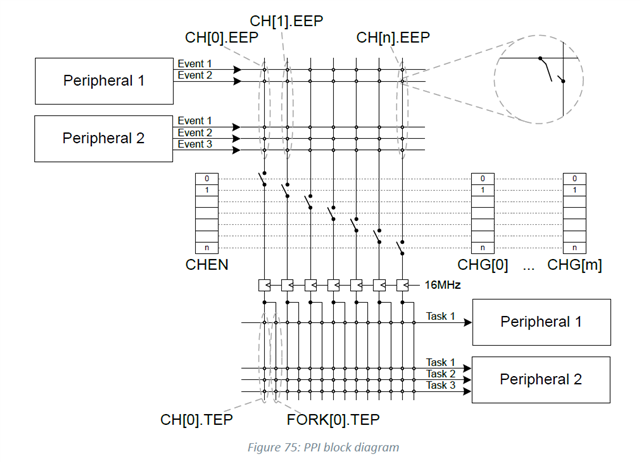
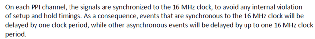
Which makes me curious, if PPI/GPIOTE aren't asynchronous they must be using a clock source. Which clock source? If it's the CPU will it be kept active during sleep/idle, in which case would the latency of doing the awake impact how quickly the event/task is processed and be the reason for the issue?

(I'm using CPU idle sleep but the level of work the CPU is doing changes which could be the reason for the randomness if the wake latency is a factor)

Thanks!

Parents
  • Hi Andrew, 
    Could you let me know the frequency of your input signal ? 
    You can read more about the clock that the PPI align to: 

    So there can be up to one clock cycle delay.

    I don't fully understand your setup, can you show it with a schematic or a figure explaining how it work ? 

  • Hi Hung,

    How is the 16MHz clock generated, half the 32MHz clock (so RC or crystal), and forced always on so long as PPI is enabled?

    How about the GPIOTE, how fast does it react to the PPI event?

    The issue isn't that it's not detecting the recovery (which at COMP 'slow mode' 1.5MHz works just fine), it's that in 'normal' 5MHz mode then either/and PPI or GPIOTE can't keep up.

    The 16MHz clock suggests it should, given 1/5MHz is plenty of tolerance.

    Regards,

    Andrew

    ###

    Flow is:

    COMP(UVLO) -> PPI -> GPIOTE -> [Toggle] -> LED_PWM_DRIVER

    Where COMP is measuring the voltage going to the LED_PWM_DRIVER. LED_PWM_DRIVER will be very fast turn-off but very slow turn-on (slow current ramp on turn-on).

Reply
  • Hi Hung,

    How is the 16MHz clock generated, half the 32MHz clock (so RC or crystal), and forced always on so long as PPI is enabled?

    How about the GPIOTE, how fast does it react to the PPI event?

    The issue isn't that it's not detecting the recovery (which at COMP 'slow mode' 1.5MHz works just fine), it's that in 'normal' 5MHz mode then either/and PPI or GPIOTE can't keep up.

    The 16MHz clock suggests it should, given 1/5MHz is plenty of tolerance.

    Regards,

    Andrew

    ###

    Flow is:

    COMP(UVLO) -> PPI -> GPIOTE -> [Toggle] -> LED_PWM_DRIVER

    Where COMP is measuring the voltage going to the LED_PWM_DRIVER. LED_PWM_DRIVER will be very fast turn-off but very slow turn-on (slow current ramp on turn-on).

Children
  • Hi Andrew,

    You can take a look at the Clock Control section in the spec:

    The HFCLK clock control receive the oscillation either from the external 32MHz crystal or the internal HFINT. It then output the PCLK16 16 Mhz to the peripherals. 

    You can choose to start the HFXO or leave it to the HFINT (default) 

    When there is a peripheral that requires PCLK16 then the HFCLK will be kept active. 

    snoopy20 said:
    How about the GPIOTE, how fast does it react to the PPI event?

    Actually it may take up to 2 cycles for the GPIOTE task to output on GPIO pin. 
    You can take a look at this ticket: 

     gpiote event -> ppi -> gpiote task latency 

    and this ticket: 
    Delay from GPIOTE Event until a Task is started over PPi on nRF52

    Seems that the latency needed is about 380ns (from GPIOTE IN event to GPIO output) 

    You can try to set NRF_POWER->TASKS_CONSTLAT = 1; to switch to constant latency mode, but I don't think it would reduce the latency in your case, as the COMP should keep the HFCLK running all the time. 

  • Hi,

    I'm already running TASKS_CONSTLAT = 1;

    I'm not using GPIOTE IN event for this part of the system (though it is in use elsewhere, but I assume doesn't effect the output of a GPIOTE channel).

    So if PPI takes 1 cycle and GPIOTE takes 2 cycles @ 16MHz that's 16/3 = 5.3MHz

    Which is close to the 5MHz "normal" mode of the COMP. Given that the behaviour is random sometimes taking minutes and sometimes hours I think there's another cycle being taken somewhere. Or maybe the 5MHz for the COMP is a ballpark figure not an absolute. It's a little close for comfort so I think the reason is potentially established.

    Regards,

    Andrew


  • Hi Andrew, 


    I agree that 5MHz is in the ballpark of the limit for the setup. I assume that reduce the COMP speed to low is an OK solution for you ? 

  • Hi,

    Yes it's been confirmed by multiple customers as working perfectly. It was really to aid my understanding and perhaps will aid others if they search similar.

    Regards,

    Andrew

Related