
Hi there!
May I know how to have UART00 on P2 like what is shown below as I wanted to have higher speed.
Is it the same as other UART assignments on P0 and P1?
Thanks!
Hi there!
May I know how to have UART00 on P2 like what is shown below as I wanted to have higher speed.
Is it the same as other UART assignments on P0 and P1?
Thanks!
Hello,
Please see the cross power-domain section of the pin assignment documentation for the nRF54L15.
What pins specifically are you trying to use? Have you used a logic analyzer to see if any of the pins are doing anything?
Best regards,
Edvin
Hi there!
I have read the link you shared before. I know it mentions dedicated pins in pin assignment table but I still want to know if I can use any P2 pins for UARTE00. For example, is it possible to use P2.06 to P2.09 for UART with flow control? I understand UART is not mentioned under description and dedicated function of P2.06 but I wanted to know if I can use it by configuration of certain registers.
Hi again,
I just changed the baud rate to 921600 in my serial port tool, then Tx of UARTE00 becomes readable text but it should be 115200 according to device tree I attached above . For Rx, it still cannot control LED of DK until I change it to P2.07 with baud rate 921600. Do you know why the actual baud rate is different from my setting and why Rx as P2.06 is not working but P2.07? Look forward to hearing from you. Thanks!
I have the same experience.
for uart00, it works only with the dedicated pin function. not able to use P2.06 for rx. try changing to P2.07.
also observed that the baud rate on the terminal program must be 8x of the uart current-speed.
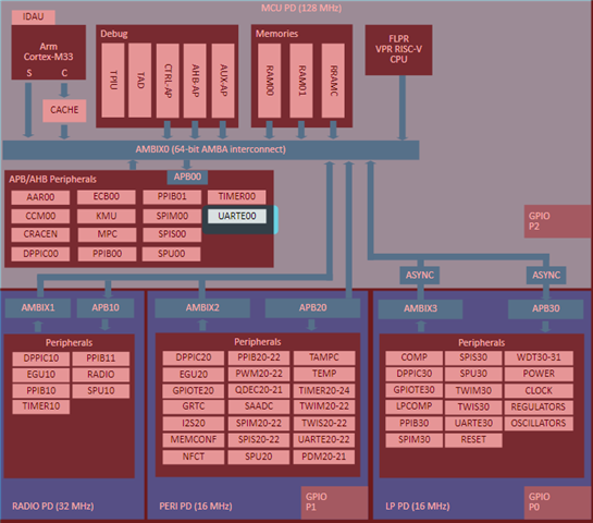
not sure if has anything to do with the peripheral clock frequency being 128 MHz in mcu domain?
jing
Hello,
Can any of you please upload the application that you are using to reproduce this. It is easier, and quicker, for me to reproduce, and potentially forward to our developers if I have something that I can just build and flash.
Best regards,
Edvin
Hi there!
I have attached my main.c, conf file, Cmake list and DTS file here.May I know what other files you need? Or should I zip the project folder and share here?
Archiet said:Or should I zip the project folder and share here?
Preferably, yes. If I don't need to create my own application on top of a CMakeLists file and a couple of scattered files, it will be a lot easier for me to reproduce, meaning I will be able to do it sooner.
Best regards,
Edvin
Archiet said:Or should I zip the project folder and share here?
Preferably, yes. If I don't need to create my own application on top of a CMakeLists file and a couple of scattered files, it will be a lot easier for me to reproduce, meaning I will be able to do it sooner.
Best regards,
Edvin
Hi there!
My computer is not with at the moment but I will do it.
Meanwhile, you can also build it by copying the sample in the link below but with UARTE00 assigned to P2.06(Rx) and P2.08(Tx) with baud rate 115200. It could be an faster alternative for your debugging. Thanks.
Hi there!
Here is the zip folder of my application.
I am using P2.08 and P2.07 as Tx and Rx of UARTE00 with pre set baud rate 115200. In this application, you should be able to use UARTE00 without problem except the actual baud rate is 921600.
Based on this application , you will find Rx is not working if you change Rx from P2.07 to P2.06.
Thank you for uploading!
Hmm... Yes, I see that it uses 921600 baudrate.
I also noticed that it says in the top row from here:
https://docs.nordicsemi.com/bundle/ps_nrf54L15/page/uarte.html#d1900e814
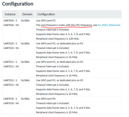
That the core frequency scales with the CPU frequency, which happens to be 8 times faster than the frequency of the other UART instance. So there is probably the reason. This however, in my opinion, should be compensated for when setting the baud rate in DeviceTree (your DTS file).
I will ask our developers if this is the intended behavior.
By the way, I see that you modified the .dts file directly. While it works, it is not the intended way to change something in devicetree. The intended way is to copy whatever you want to change from the .dts or .dtsi files, create your own file called <board_name>.overlay, and place it in your application folder. (in this case, that would be nrf54l15dk_nrf54l15_cpuapp.overlay), and paste whatever you want to modify into that file. Then, in the overlay file, you can change whatever you want to. I'll attach your modified project, including the .overlay file, for reference.
Best regards,
Edvin
Hi there!
Thanks for the hint regarding overlay file.
On the other hand, are you able to use P2.06 as Rx? If yes, could you share what you have made with me so I could follow? Thanks!
Sorry. I missed that part.
You can't use P2.06 for UARTE00. You can look in the pin Assignment (Table 3) on this site what pins you can use for UARTE00. On P2, you can use:
P2.00
P2.02
P2.04
P2.05
P2.07
P2.08
P2.09
P2.10
I tested just now, and it worked only replacing this line:
psels = <NRF_PSEL(UART_TX, 2, 8)>, <NRF_PSEL(UART_RX, 2, 6)>;
with e.g.psels = <NRF_PSEL(UART_TX, 2, 8)>, <NRF_PSEL(UART_RX, 2, 7)>;
Best regards,
Edvin

