How to verify that the 32MHZ crystal is actually working (nRF52832?

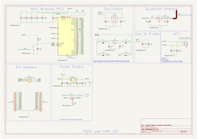
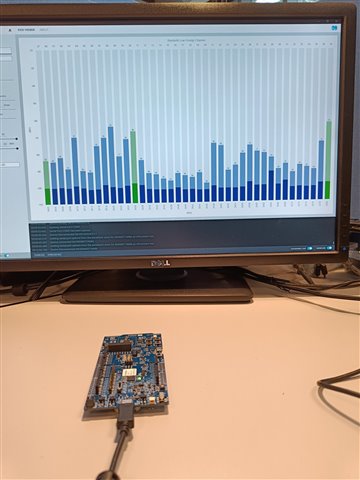
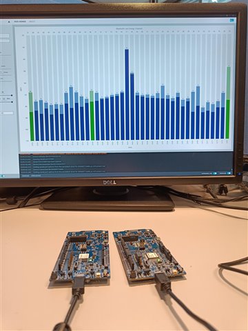
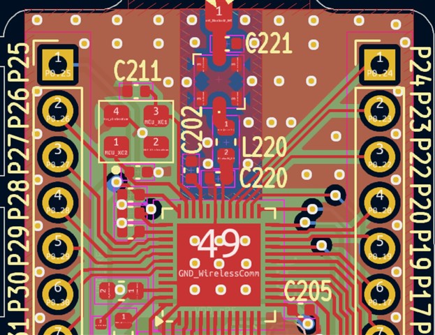
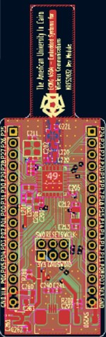
I am using nRF connect SDK v2.9.0 with a custom developed board that looks like this:

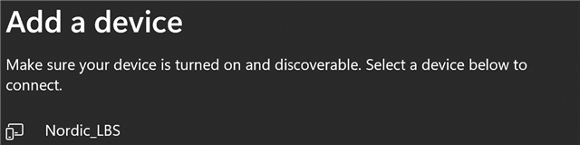
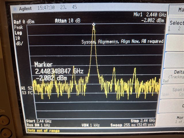
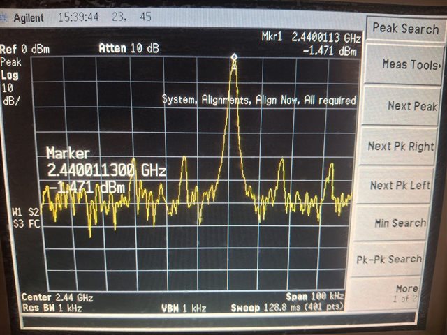
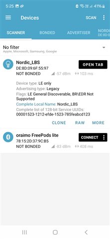
I tried the 'Bluetooth LE LED Button service' sample as it's and noticed that nothing was working. I grapped my logic analyzer and hooked it up onto the 32MHZ but nothing is showing. I mean other functionalities like zepyrRTOS, PWM, GPIOs, I2C, etc...  are working successfully but not BLE.

does the nRF52832 have an internal clock through which it works by default and if so, how does it use the external clock. what is the first thing to debug?

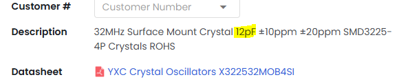
this is the crystal I am using:

https://www.lcsc.com/product-detail/Crystals_YXC-Crystal-Oscillators-X322532MOB4SI_C9009.html 

and these are the schematics:

Parents
  • Hi there, 

    You can use the radio test sample to check if the radio works, you can select const carrier and sett 0 og +4dBm as output and then you should see something with an RSSI viewer. 

    Or you can use this HEX, it just puts the device on constant carrier on channel 40 (2440MHz). 
    8267.nrf52 carrier ch40 4dBm.hex


    Open you can use the nRF52 DK as a RSSI viewer, 

    This is what it would look like if you have just normal (office) background noise. 


    And this is what it would look like if the radio is sending a constant carrier on the selected channel. 

    It does not show if the 32MHz crystal is correctly loaded as the PPM is not really measurable this way, but it does show if there is something going on at least. 

    See: https://devzone.nordicsemi.com/guides/hardware-design-test-and-measuring/b/nrf5x/posts/general-pcb-design-guidelines-for-nrf52-series 


    Also we do HW reviews here so for future projects feel free to ask for a second pair of eyes to have a look at the design. 


    Regards,
    Jonathan

  • Hi Mr.Jonathan.

    Sorry for the late reply but I used a spectrum analyzer to make sure there was a signal being transmitted and I actually could see some peaks temporarily in the 2.4 to 2.5 GHZ bandwidth.

    However, the nRF52 BLE can be seen on my laptop but not via nRF connect app on my android mobile phone:

    when I tried to connect to it via my laptop, it gave me an error and I can see from the logs on the nRF52 side these logs:

    so the antenna is working but is there anything to be modified from the nRF Connect App side for such an error?

  • I have made the tests that were discussed before, I downloaded the .hex file you provided to me before and here are the results:

    This is the output of the ANT pin on the spectrum analyzer without being connected to the Antenna or the matching network:

    As you can see, there is a peak at 2.44 GHZ. I then used the nRF52840 USB dongle as an RSSI viewer, and here are the results:

    Before powering the MCU:

    After powering the MCU, where both of the boards are placed closely together:

    There is a clear peak at 2.4 GHZ.


    Nevertheless, when I programmed the MCU with the Bluetooth sample example,, the mobile app doesn't detect the presence of any Bluetooth devices:

    I have this mobile app with another MCU vendor for Bluetooth connectivity (BLE 5.3), and it worked successfully, so I don't think it's the mobile app but rather the code. I can't seem to know what's wrong with the code. I am using the 32 KHZ crystal oscillator that's required by the example code. All of the functions being called in the code doesn't return any errors. 

  • Looks like the radio is working at least, so that seems to be in order. 

    It might be that the 32MHz clock is a bit off. Can you sett the Resolution bandwidth to 1kHz and View bandwidth to 1kHz. Then we can see how accurate the carrier signal is. 

    Ideally you should have something that looks like this:
       

    So if the carrier offset is bad then things like this can happen. 


    Regards,
    Jonathan

  • I have done the test and noticed the following:

    At central frequency = 2.44 GHZ and the span = 100KHZ -:

    At central frequency = 2.44 GHZ and the span = 1MHZ -:

    At central frequency = 2.4403 GHZ and the span = 100KHZ -:

    Note that I didn't remove a 0.8pF capacitor on the ANT pin Side, meaning that the ANT pin is connected directly to the spectrum analyzer, and the 0.8pF capacitor is connected between the ANT pin and the ground.

  • Thanks for all the info. 

    So the crystal you have does do its thing but it does it badly. It is 350kHz off the wanted frequency here so that is why you have issues. Its way outside the spec. 

    You can try and load the crystal with some other caps to see if you can get it closer but not sure you will be able to get it all the way. 

    If you have 12pF caps no try to use 22pF and check the center freq again. 

    Might need a new crystal. 

    Regards,
    Jonathan

  • ok, I will try with new crystal load caps, but as mentioned in the post, this is the crystal I am using with a 7 pF load capacitor:

    https://www.lcsc.com/product-detail/Crystals_YXC-Crystal-Oscillators-X322532MOB4SI_C9009.html 

    I will try to change its capacitance values, but is it or is it not out of spec?

Reply Children
No Data
Related