Issue creating and using binding files for SPI

Hi all, will need to post short as I am getting a "cannot create ticket" error.

Hi all,

I'm quite new to nrf, zephyr and embedded of this complexity but have completed the fundamentals and intermediate courses.

My intention is to get SPI set up for a TI ADS1298 chip connected to my nrf52DK/52832 board. The only way I know to do this is via bindings and as shown in the lessons and if there is a better way for a custom device with this SPI device connected and an SPI SD card (backup for later BLE comms), please let me know..

I am trying to create a new binding file for the ADS1298 so I can get communication in a similar way to the intermediate course SPI module.

I am working on SDK v2.8.0 in VSCode.

I have created a new blank project and tried to create my own binding file, keeping it simple. Basic file structure within the project is as follows:

my_app
|___ build |___ src |___ prj.conf |___ CMakeLists.txt |___ dts |___ bindings |___ sensor
|___ ti,ads1298.yaml

I have not edited the CMakeLists.txt file.
Parents Reply
  • Hi hmolesworth,

    This support is a veritable mountain of info, much appreciated. Its the same situation and setup as myself. I am fully aware of the power on sequence and have hopefully already accounted for the 4xtclk delay mentioned in this thread. I too plan on manually controlling \CS within a function to account for this delay but lowering the SCLK to 500kHz is a good idea. Hopefully my test sequence works better than the OP, I have already accounted power on time but should probably monitor the AVDD and DVDD.

Children
  • Another alternative is using SPIM TASKS_SUSPEND and TASKS_RESUME coupled via PPI to a timer to provide the required delay which then allows a much higher clock speed. I never got around to trying that.

  • That is certainly a good idea suspending the task. Hopefully I will have time to try that and let you know. running at a higher clock speed would be nice to reduce power.

  • FYI, I have some clarification and proof about the multibyte delay:

    9.5.2.9: ADS129x Datasheet

    However, if SCLK is 4 MHz, one byte is transferred in 2 µs. Because this transfer time exceeds the tSDECODE specification, the processor can send subsequent bytes without delay. In the second scenario, the serial port can be programmed to use multiple byte transfers instead of the single-byte transfers required to meet the timing of the first scenario.

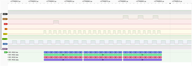
    I have scoped the ADS1298 PDK running using the TI evaluation software.

    The attached image shows the PDK outputting a two byte command read and getting a response whilst using a 4MHz clock. The need to run with a 4* t_CLK space is not required. I would assume that the ADS129x spi rx register can still receive spi data but cannot act upon the next byte received within 4* t_CLK, this clarifies this section.

Related