PaWR power consumption

Hi,

MCU - nRF52832


I am trying to understand the power consumed during the PaWR operation. I am referring to the steps explained here:

Periodic Advertising with Responses (PAwR): A practical guide

I am getting the a similar graph shown in the above page. I have few questions regarding this.


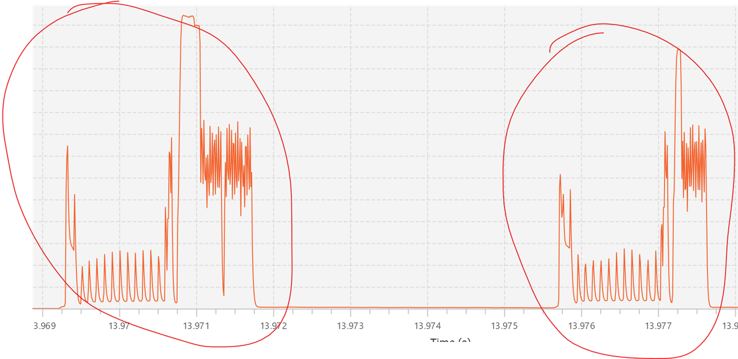
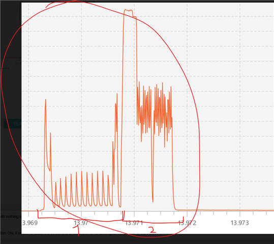
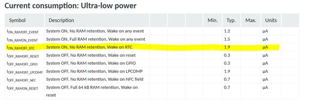
  1. Between the peeks, I observe a current of 1.9 uA. Is this expected ? If I understand it correctly, the mcu should be in systemON between advertising events and this should not consume more than 1uA 

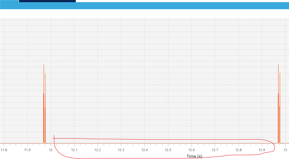
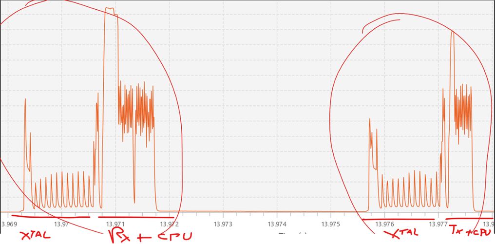
2. If I zoom into to one of the peeks, it looks like two events are happening. Do we know what exactly is happening here ? I am presuming the first one is when the MCU is receiving the subevent and the second one is when the mcu is sending the response. Is this correct ?

Parents
  • Hello,

    I observe a current of 1.9 uA. Is this expected ?

    The product specification says 1.2µA. But that is a bare minimum. System ON sleep with nothing else going on, and no RAM retention:

    https://docs.nordicsemi.com/bundle/ps_nrf52832/page/power.html#d935e27684

    So I wouldn't say that 1.9µA is unexpected. Remember that in addition to being in System ON, it needs to retain the RAM, and at least a timer is running, to keep track of the next PAwR event. 

    Do we know what exactly is happening here ?

    I don't know how familiar you are with "Normal BLE", but in PAwR this is switched around. In "Normal BLE" you would have one device advertising, waiting for a scanner to pick up the advertisement, and then issue a Connect request directly after the advertisement. So the advertiser would then do a TX on the radio, followed by a short RX to check if there are any connection requests.

    In PAwR, this is, as I said, switched up. From section 2.2 in the link you provided:
    The network relies on one single advertiser acting as the gateway/access point. This means all nodes in the network must be in the range of the advertiser. It's possible to expand the network with multiple advertisers, but the spec doesn't define how such a network should be set up.

    So you have one device being the central/gateway of the other devices. This is the one that advertises periodically. The one that you are looking at is the device that scans for these advertisements. So this device, from your plots, will first do an RX (marked with 1 in the below figure), followed by a TX (marked with 2). So yes, your assumption is correct. 

    Best regards,

    Edvin

  • I seem to be mistaken. It is correct as you said. The first one is the initial event, and the second one is the reply. So disregard what I wrote in my previous reply. 

    If you look closer on each of the events, what we see is the HFCLK starting up (the HFXTAL), then you have the peak, which is the radio (RX or TX), and then there is post processing from the CPU.

    The 1.9µA is also expected. The current consumption expected for System on and wake on RTC is actually 1.9µA as seen here:

  • just to put it in another way: 
    - first activity, the HF XTAL ramps up. and there is a Rx activity (to receive the PA sync message from the central), followed by CPU processing. Since the response slot is far from this Rx activity, we optimize power consumption by switching off the HF XTAL
    - second activity, you see the HF XTAL ramps up again, and then response is sent to the central (TX and postprocessing CPU). 

    In this case, it seems the response slot delay is quite long, that is why you see such distance between Rx and Tx. By playing with Response slot delay and response slots and other timings, the distance between these two may be different. 

Reply
  • just to put it in another way: 
    - first activity, the HF XTAL ramps up. and there is a Rx activity (to receive the PA sync message from the central), followed by CPU processing. Since the response slot is far from this Rx activity, we optimize power consumption by switching off the HF XTAL
    - second activity, you see the HF XTAL ramps up again, and then response is sent to the central (TX and postprocessing CPU). 

    In this case, it seems the response slot delay is quite long, that is why you see such distance between Rx and Tx. By playing with Response slot delay and response slots and other timings, the distance between these two may be different. 

Children
No Data
Related