COMP (or PPI) drops event

Hi,

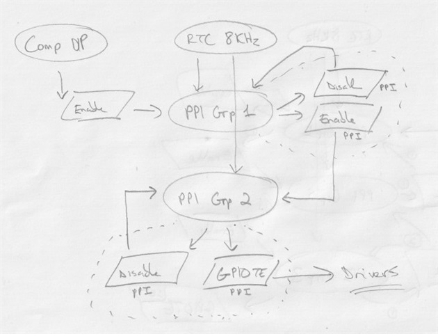
I previously wrote about an unexpected behaviour which I've made a diagram for below. It's relatively simple though, the COMP watches a voltage and fires a toggle event through PPI which is received by GPIOTE which toggles it's pin which controls an external circuit responsible for the voltage that COMP watches.

First the external circuit is switched off by a secondary means and the system is synced, so GPIOTE goes high and COMP goes high, then the secondary means is turned off so the driver activates and then it's purely a hardware based implementation.

I previously replicated the behaviour when the COMP speed was set to normal. This suggested that PPI or GPIOTE couldn't keep up with the events it was generating OR COMP was/is sometimes failing to generate the toggle event when the voltage has recovered. The behaviour means the GPIOTE remains low when the voltage has recovered.

The COMP speed was set to low, so 1MHz, and on the bench this appeared to have resolved the issue. However, a user is now reporting it again.


Parents
  • The main issue here seems to be that your loop here seems very fragile where it depends on toggling instead of relying on a deterministic state.

    My suggestion is that you can map

    COMP->EVENT_UP → GPIOTE TASKS_SET
    COMP->EVENT_DOWN → GPIOTE TASKS_CLR

    So that we are sure that the ping goes high if the voltage goes above threshold and vice versa.

  • I don't see why it's fragile, only the COMP generates the signal and only COMP has control over the 'thing' that affects the signal. It's closer to a true hardware UVLO implementation this way.

    Originally many moons ago I had implemented it by the method you describe but found it didn't work, probably because the comp was generating the events too close together and they were racing to be processed. This may however have been with the COMP on normal or fast speed and may be worth a revisit, but I have my doubts whether it will fix the underlying issue.

    I should elaborate further. The external circuit is a slow turn-on (ramps) but a fast off. This will mean when the COMP generates its below signal triggering gpiote the above signal is going to follow quickly. Indeed it is this above signal which is 'missing' on occasion. 

    I know that setting the COMP to slow almost fixes the issue.

  • snoopy20 said:
    many moons ago I had implemented it by the method you describe but found it didn't work, probably because the comp was generating the events too close together and they were racing to be processed. This may however have been with the COMP on normal or fast speed and may be worth a revisit, but I have my doubts whether it will fix the underlying issue.

    Would have been nice to know why this did not work. What initial triggers missed? or was it after some time that this did not work? There seems to be something we might have missed if this setup did not work. It should have worked.

  • Same behaviour, the TASKS_SET either didn't fire or was ignored by PPI or GPIOTE.

    As I see it the reasoning in both cases has to be one of:

    1. the COMP despite being in 'slow' is still able to overwhelm PPI or GPIOTE timing. In a previous post I determined with one of Nordic staff that the 'normal' mode (5MHz) might be pushing it, but 1MHz should be fine for PPI/GPIOTE processing.

    2. The upper hysteresis resistor is set to trigger at 4.8v (nominal voltage is 5v +/- 1%). The tolerance of the comp hysteresis is unknown, does it change with temperature, does the comp speed change the tolerance (it does on PIC16 as an example)?

    I'm still thinking it's around (1) because switching to 'slow' almost resolved it. I'm thinking there's something around PPI or GPIOTE reaction speed.

    This errata says a clock is used for GPIOTE input events > 750KHz. I wonder what clock and whether it also applies for output events...

    docs.nordicsemi.com/.../anomaly_810_155.html


  • Hi snoopy20,

    Susheel had to go on a sick leave, and I will support you in his stead.

    I will have to ask our IC engineers regarding the question about tolerance variance and the errata. However, please understand that the easter holiday has started, so that might take some time. Our apologies for the inconvenience.

    I would like to understand your system a little more.

    Does the external circuit react to the edge, or to the level of the GPIOTE signal?
    Can it be changed to react to the level of the GPIOTE signal instead? Ideally with some kind time-based debouncing.

    For the input signal, is there any chance of jitter? Have you tried to connect the GPIOTE signal and COMP input to a scope and monitor for any incorrect behavior?

  • Hi Hieu,

    It's not of great urgency. Currently I can't replicate it on the bench (switching to 1MHz fixed it for me). I have two production users that are trying to replicate, when it does they can capture evidence in the accompanying App.

    The output is a TLV62090. The input is analog, there is no jitter. So long as PPI/GPIOTE are faster then COMP then COMP monitors and controls the circuit.

    I use the NRF52's pull-up and high disconnect config as a secondary override so COMP state and GPIOTE state remain in sync, and the TLV62090 has a soft-start. The turn-on will therefore be much slower then the turn-off. When the COMP turns the TLV62090 off the voltage will recover fast and of course this appears to be what it has trouble capturing.

    I can only see that it is capturing the recovery too close to the turn-off point, that is to say COMP is overwhelming PPI or GPIOTE. There is no other logical explanation.

    The only other reason would be the upper hysteresis point of the COMP becomes invalid, so as the voltage rises it no longer strikes a match. I don't do anything special here, the value is set on boot and reasonably below the recovery voltage to ensure it strikes with a good margin (4.8v vs 5.0, 1% resistor divider then whatever the % deviance of the internal res/hys is of the COMP). Unless there's a lot of variance around temperature - my users will be in different outdoor environments likely ranging from 0-30c at the moment. The CPU temperature will be captured in the App as well.


Reply
  • Hi Hieu,

    It's not of great urgency. Currently I can't replicate it on the bench (switching to 1MHz fixed it for me). I have two production users that are trying to replicate, when it does they can capture evidence in the accompanying App.

    The output is a TLV62090. The input is analog, there is no jitter. So long as PPI/GPIOTE are faster then COMP then COMP monitors and controls the circuit.

    I use the NRF52's pull-up and high disconnect config as a secondary override so COMP state and GPIOTE state remain in sync, and the TLV62090 has a soft-start. The turn-on will therefore be much slower then the turn-off. When the COMP turns the TLV62090 off the voltage will recover fast and of course this appears to be what it has trouble capturing.

    I can only see that it is capturing the recovery too close to the turn-off point, that is to say COMP is overwhelming PPI or GPIOTE. There is no other logical explanation.

    The only other reason would be the upper hysteresis point of the COMP becomes invalid, so as the voltage rises it no longer strikes a match. I don't do anything special here, the value is set on boot and reasonably below the recovery voltage to ensure it strikes with a good margin (4.8v vs 5.0, 1% resistor divider then whatever the % deviance of the internal res/hys is of the COMP). Unless there's a lot of variance around temperature - my users will be in different outdoor environments likely ranging from 0-30c at the moment. The CPU temperature will be captured in the App as well.


Children
Related