COMP (or PPI) drops event

Hi,

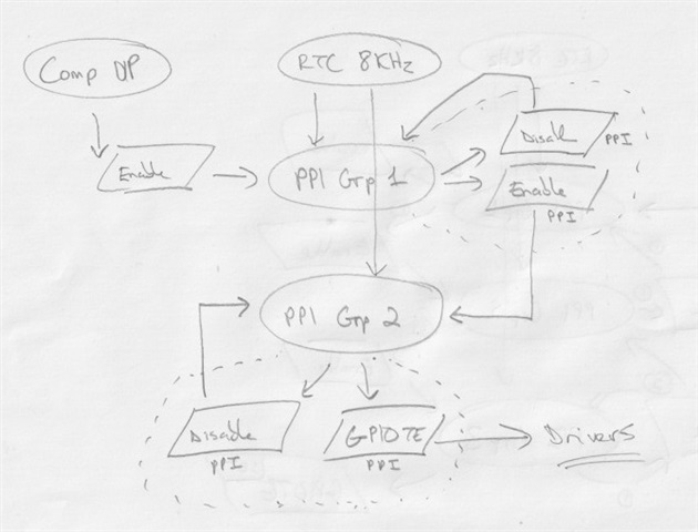
I previously wrote about an unexpected behaviour which I've made a diagram for below. It's relatively simple though, the COMP watches a voltage and fires a toggle event through PPI which is received by GPIOTE which toggles it's pin which controls an external circuit responsible for the voltage that COMP watches.

First the external circuit is switched off by a secondary means and the system is synced, so GPIOTE goes high and COMP goes high, then the secondary means is turned off so the driver activates and then it's purely a hardware based implementation.

I previously replicated the behaviour when the COMP speed was set to normal. This suggested that PPI or GPIOTE couldn't keep up with the events it was generating OR COMP was/is sometimes failing to generate the toggle event when the voltage has recovered. The behaviour means the GPIOTE remains low when the voltage has recovered.

The COMP speed was set to low, so 1MHz, and on the bench this appeared to have resolved the issue. However, a user is now reporting it again.


Parents
  • The main issue here seems to be that your loop here seems very fragile where it depends on toggling instead of relying on a deterministic state.

    My suggestion is that you can map

    COMP->EVENT_UP → GPIOTE TASKS_SET
    COMP->EVENT_DOWN → GPIOTE TASKS_CLR

    So that we are sure that the ping goes high if the voltage goes above threshold and vice versa.

  • I don't see why it's fragile, only the COMP generates the signal and only COMP has control over the 'thing' that affects the signal. It's closer to a true hardware UVLO implementation this way.

    Originally many moons ago I had implemented it by the method you describe but found it didn't work, probably because the comp was generating the events too close together and they were racing to be processed. This may however have been with the COMP on normal or fast speed and may be worth a revisit, but I have my doubts whether it will fix the underlying issue.

    I should elaborate further. The external circuit is a slow turn-on (ramps) but a fast off. This will mean when the COMP generates its below signal triggering gpiote the above signal is going to follow quickly. Indeed it is this above signal which is 'missing' on occasion. 

    I know that setting the COMP to slow almost fixes the issue.

  • Hi Hieu,

    It's not of great urgency. Currently I can't replicate it on the bench (switching to 1MHz fixed it for me). I have two production users that are trying to replicate, when it does they can capture evidence in the accompanying App.

    The output is a TLV62090. The input is analog, there is no jitter. So long as PPI/GPIOTE are faster then COMP then COMP monitors and controls the circuit.

    I use the NRF52's pull-up and high disconnect config as a secondary override so COMP state and GPIOTE state remain in sync, and the TLV62090 has a soft-start. The turn-on will therefore be much slower then the turn-off. When the COMP turns the TLV62090 off the voltage will recover fast and of course this appears to be what it has trouble capturing.

    I can only see that it is capturing the recovery too close to the turn-off point, that is to say COMP is overwhelming PPI or GPIOTE. There is no other logical explanation.

    The only other reason would be the upper hysteresis point of the COMP becomes invalid, so as the voltage rises it no longer strikes a match. I don't do anything special here, the value is set on boot and reasonably below the recovery voltage to ensure it strikes with a good margin (4.8v vs 5.0, 1% resistor divider then whatever the % deviance of the internal res/hys is of the COMP). Unless there's a lot of variance around temperature - my users will be in different outdoor environments likely ranging from 0-30c at the moment. The CPU temperature will be captured in the App as well.


  • I have confirmation and evidence from a user showing it's real.

    I'm about to replicate his exact settings at this end but so far I've been unable to reproduce, the COMP is firing correctly here. My unit is at 23c and his is at 9c CPU temperature, I'll freeze mine later and see if there's a change.


  • Alrighty, so I can now replicate it on the bench. It takes a lot longer but usually 5-10 minutes of UVLO activity will eventually cause it.

    So far it occurs with the CPU at 9 or 25c, so discounting temperature.

    When it occurred I was watching the state of the system in the App and no event fired which would/might/possibly - have done anything that I can possibly thing would be related.

    I tried applying https://docs.nordicsemi.com/bundle/errata_nRF52810_Rev3/page/ERR/nRF52810/Rev3/latest/anomaly_810_155.html but with no luck.

    The COMP sample output also goes to the App so I can see it is reporting power is above the reference.

    Finally I snuck a little hidden feature in so I can manually fire the GPIOTE TASK_SET which confirms it hasn't crashed internally (if that's even possible) and also confirms the external driver is working correctly.

    I have to conclude this is a hardware issue being:

    1. sometimes the COMP doesn't generate an event for an EVENT_UP (or cross) or
    2. PPI is overwhelmed by the speed of COMP in low/slow mode (1MHz) or
    3. GPIOTE is overwhelmed by the speed of COMP in low/slow mode (1MHz)

  • And finally for tonight another observation.

    I decided to go back and retry the SET/CLR method, but I only implemented for one of the three external drivers (all of which do the same thing).

    The SET/CLR method failed first, so is worse.

    It pretty much validates my hypothesis, PPI or GPIOTE can't keep up with the speed of COMP in it's lowest speed. This is quite troubling as I have no mitigation for it.

  • I kept at it and may have a solution, it appears to be working so far.

    I don't have any timers left but have an RTC ticking at 8KHz.

    I wire the COMP UP event to enable a PPI group. Two PPI's linked to the RTC tick fire the GPIO SET and disable the PPI group.

    Questions are:

    1. If the COMP UP event and the RTC tick event come in at the same time will the enabling of the group also fire the PPI on the same clock? It seems unlikely, but possible.

    2. If the COMP UP event comes in and the RTC tick is one peripheral clock later, then the added delay is just 1/16MHz. This is still much faster then the 1MHz of the COMP, which is known to be fast enough to create the original issue.

    So far though it appears to be a solution. As long as enabling the PPI grp and the PPI event it controls firing at the same time won't actually trigger the PPI (aka 1) then I will wire in a second GRP also working on the RTC tick, which will avoid (2). Thus, the outputs will be SET on the second RTC tick.


Reply
  • I kept at it and may have a solution, it appears to be working so far.

    I don't have any timers left but have an RTC ticking at 8KHz.

    I wire the COMP UP event to enable a PPI group. Two PPI's linked to the RTC tick fire the GPIO SET and disable the PPI group.

    Questions are:

    1. If the COMP UP event and the RTC tick event come in at the same time will the enabling of the group also fire the PPI on the same clock? It seems unlikely, but possible.

    2. If the COMP UP event comes in and the RTC tick is one peripheral clock later, then the added delay is just 1/16MHz. This is still much faster then the 1MHz of the COMP, which is known to be fast enough to create the original issue.

    So far though it appears to be a solution. As long as enabling the PPI grp and the PPI event it controls firing at the same time won't actually trigger the PPI (aka 1) then I will wire in a second GRP also working on the RTC tick, which will avoid (2). Thus, the outputs will be SET on the second RTC tick.


Children
  • Hi snoopy20,

    Firstly, regarding your conclusion that either PPI or GPIOTE isn't able to keep up with 1MHz COMP, I will have to ask about this in my internal query as well before I can confirm it.

    However, I am still unclear on one detail. Does the system run in some kind of loop then? And what is the frequency of looping then?

    Secondly, here is my understanding of the system, please correct me if I am wrong.

    • It is meant to be a UVLO monitoring VDD
    • The TLV62090 converts VDD to a lower voltage for a sink
    • The COMP+PPI+GPIOTE setup controls the TLV62090

    I think I am missing a few more things:

    • How the TLV62090 and later circuits affects VDD? Is it just a voltage dip due to sudden loading?
    • How frequently does this loop repeat?
    • Can you give a state machine showing how the COMP, GPIOTE, and TLV62090 are supposed to work together?

    Thirdly, regarding the RTC workaround you are setting up, could you please tell me exactly which PPI event is connected to which PPI tasks over which PPI channels, one at a time?

  • The frequency of the loop is dictated by the speed of the COMP, which in low power mode is 1MHz according to the datasheet.

    Your understanding of the system is correct. Then your third points are:

    1. correct, if the sink is too much VDD will drop
    2. the speed of the missing event (Vdd recovered) is dependent on how fast TLV62090 turns off and then how fast COMP toggles its state. The turn off by TLV62090 will be very fast, microseconds at worst. The state (Vdd recovered) is then waiting for COMP to detect it.
    3. there's really not much to it. COMP detects Vdd, state goes to PPI/GPIOTE and toggles thing which affects Vdd, so equilibrium.

    The PPI GRP workaround is a success (the RTC is just to clock, could use anything). I've ran it for hours.

    The solutions slows down the EVENT_UP propagation and so clearly tells me the problem is not with COMP or PPI because it's now working, so the problem is with GPIOTE. It isn't fast enough to handle 1MHz PPI events.

      // GPIOTE turn-offs
      NRF_PPI->CH[CFG_PPI_POWERMANAGER_UVLO_FRONTREAR].EEP = (uint32_t) &NRF_COMP->EVENTS_DOWN;
      NRF_PPI->CH[CFG_PPI_POWERMANAGER_UVLO_FRONTREAR].TEP = (uint32_t) &NRF_GPIOTE->TASKS_CLR[CFG_GPIOTE_POWERMANAGER_FRONT];
      NRF_PPI->FORK[CFG_PPI_POWERMANAGER_UVLO_FRONTREAR].TEP = (uint32_t) &NRF_GPIOTE->TASKS_CLR[CFG_GPIOTE_POWERMANAGER_REAR];
    
      // -- enables first group, awaits a tick
      NRF_PPI->CH[CFG_PPI_POWERMANAGER_UVLO_GROUP].EEP = (uint32_t) &NRF_COMP->EVENTS_UP;
      NRF_PPI->CH[CFG_PPI_POWERMANAGER_UVLO_GROUP].TEP = (uint32_t) &NRF_PPI->TASKS_CHG[CFG_PPI_GROUP_POWERMANAGER_ENABLE_NEXT].EN;
    
      // -- enables next group on tick, disables self (one shot)
      NRF_PPI->CH[CFG_PPI_POWERMANAGER_TIMER_GROUP_NEXT].EEP = (uint32_t) &CFG_SCHEDULER_TIMER->EVENTS_TICK;
      NRF_PPI->CH[CFG_PPI_POWERMANAGER_TIMER_GROUP_NEXT].TEP = (uint32_t) &NRF_PPI->TASKS_CHG[CFG_PPI_GROUP_POWERMANAGER_ENABLE_NEXT].DIS;
      NRF_PPI->FORK[CFG_PPI_POWERMANAGER_TIMER_GROUP_NEXT].TEP = (uint32_t) &NRF_PPI->TASKS_CHG[CFG_PPI_GROUP_POWERMANAGER_ENABLE_SET].EN;
      NRF_PPI->CHG[CFG_PPI_GROUP_POWERMANAGER_ENABLE_NEXT] = 1 << CFG_PPI_POWERMANAGER_TIMER_GROUP_NEXT;
    
      // -- sets outputs, disables self (one shot)
      NRF_PPI->CH[CFG_PPI_POWERMANAGER_TIMER_FRONTREAR].EEP = (uint32_t) &CFG_SCHEDULER_TIMER->EVENTS_TICK;
      NRF_PPI->CH[CFG_PPI_POWERMANAGER_TIMER_FRONTREAR].TEP = (uint32_t) &NRF_GPIOTE->TASKS_SET[CFG_GPIOTE_POWERMANAGER_FRONT];
      NRF_PPI->FORK[CFG_PPI_POWERMANAGER_TIMER_FRONTREAR].TEP = (uint32_t) &NRF_GPIOTE->TASKS_SET[CFG_GPIOTE_POWERMANAGER_REAR];
      NRF_PPI->CH[CFG_PPI_POWERMANAGER_TIMER_GROUP_SET].EEP = (uint32_t) &CFG_SCHEDULER_TIMER->EVENTS_TICK;
      NRF_PPI->CH[CFG_PPI_POWERMANAGER_TIMER_GROUP_SET].TEP = (uint32_t) &NRF_PPI->TASKS_CHG[CFG_PPI_GROUP_POWERMANAGER_ENABLE_SET].DIS;
      NRF_PPI->CHG[CFG_PPI_GROUP_POWERMANAGER_ENABLE_SET] = 1 << CFG_PPI_POWERMANAGER_TIMER_FRONTREAR | 1 << CFG_PPI_POWERMANAGER_TIMER_GROUP_SET;


    I hope you like the solution, I'm pretty pleased with myself. With NRF52 there's always a way. Sunglasses


  • I am afraid I am unqualified to comment on this solution Sweat smile. I see what you are doing, but I lack the knowledge to evaluate it.

    But it's great to know that you have a working solution now.

    I will follow-up regarding the unanswered questions once I receive a response for my internal query. However, it looks like that has to be after the Easter holiday. My apology for the inconvenience.

Related