custom nRF5340 board no bluetooth signal

Hi Community,

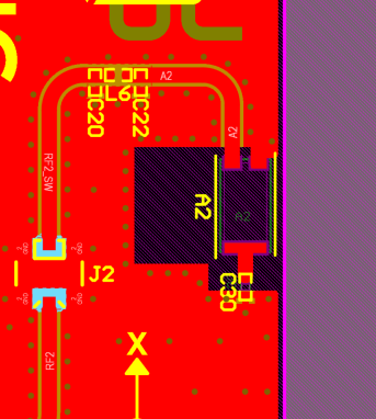
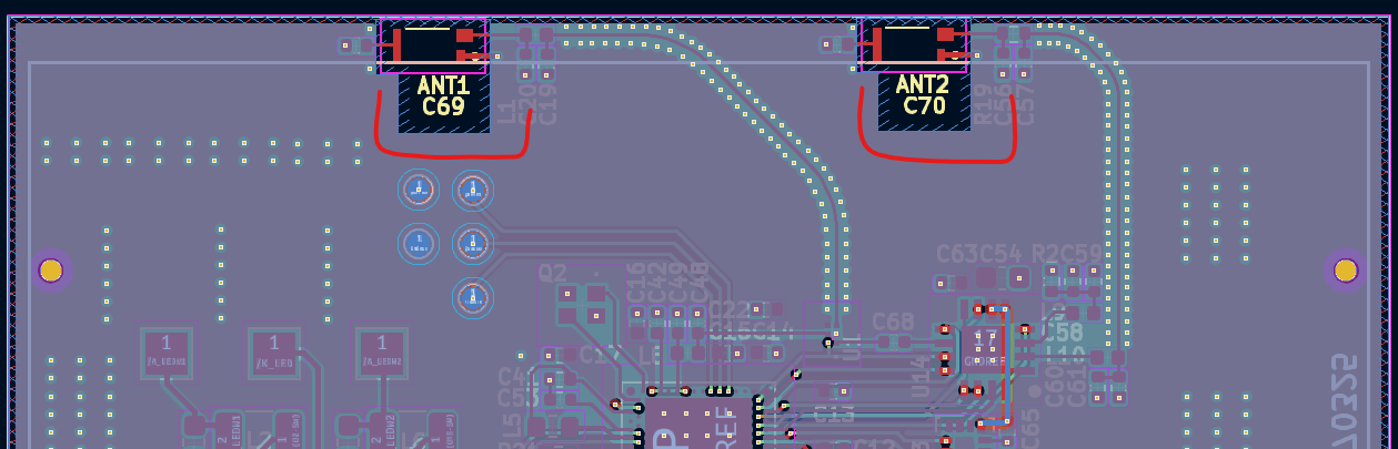
I designed a similar board asThingy53, espacially the antenna parts are almost the same, except the RF switch, we replace it with another one (BGS12WN6E6327XTSA1), then we found there is some issue to make the switch work properly, so I just removed the RF switch and short the RF output to the short range antenna, which means, now only one anntenna is connected to the RF, even so, I cannot see any RF signal on the mobile phone. 

but the output from UART seems no problem:

*** Booting nRF Connect SDK v3.5.99-ncs1 ***
[00:00:00.303,100] <inf> Custom_board: Starting Custom_board...

[00:00:00.309,020] <inf> fs_nvs: 8 Sectors of 4096 bytes
[00:00:00.309,020] <inf> fs_nvs: alloc wra: 0, fd0
[00:00:00.309,051] <inf> fs_nvs: data wra: 0, 1c
[00:00:00.334,167] <inf> bt_hci_core: HW Platform: Nordic Semiconductor (0x0002)
[00:00:00.334,197] <inf> bt_hci_core: HW Variant: nRF53x (0x0003)
[00:00:00.334,228] <inf> bt_hci_core: Firmware: Standard Bluetooth controller (0x00) Version 54.58864 Build 1214809870
[00:00:00.336,456] <inf> bt_hci_core: No ID address. App must call settings_load()
[00:00:00.338,897] <inf> bt_hci_core: Identity: E6:BD:87:6D:09:49 (random)
[00:00:00.338,928] <inf> bt_hci_core: HCI: version 5.4 (0x0d) revision 0x218f, manufacturer 0x0059
[00:00:00.338,928] <inf> bt_hci_core: LMP: version 5.4 (0x0d) subver 0x218f
[00:00:00.342,742] <inf> Custom_board: Bluetooth initialized

[00:00:00.348,327] <inf> Custom_board: Advertising successfully started

the same code, if I compiled it for the nRF5340DK, the bluetooth signal can be observed. 

So I just curious if I did something wrong in my board files or something else? 

I have been strugled in this issue for a long time, please help me with it, thanks a lot!

Best regards

Danny

Parents
  • Have you hade the design fully reviewed by us? 


    My guess is that there is an issue with the antenna or RF path in some way and that this impacts the range, so maybe you need to be very close, try a few centimeters. And only have the PCB, if there is any casing or other material in the way or enclosing the antenna\PCB this might be a reason to why the RF is bad. 


    Alternatively it might be the the clock, the 32MHz might be off and that can contribute to the issue. Make sure it is loaded correctly. 

    Regards,
    Jonathan

  • Hi   

    1. it's not reviewed by you. I just checked the Thingy53 PCB file, found the followed differences:

    Thingy53 PCB:

    trace width: 0.6mm

    grounded vias around the clear area of antenna .

    My PCB:

    trace width: 0.18mm:

    I used this calculation, therefore I used 0.18mm RF trace width, is there anything wrong?

    forgot to put grounded vias around the clear area of antenna.

    I even put the PCB very close to the mobile phone, still can not see any siganl from my PCB.

    2. I think I checked the 32M Hz crystal before, it's running, and all the other peripherals are running correctly, I2C, SPI, PWM...


    Best regards
    Danny

  • Hi Danny,

    The "No backend available" error comes from a missing libusb-1.0.dll.

    This should have been installed by the libusb-package in the requirements.txt file.

    Do you have multiple python versions installed on this computer?

    If so, did you run the pip install command using the same python version you are using for running the application?


    It is possible to install this dll manually. It can be downloaded form the libusb github repository(in the .7z file):

    https://github.com/libusb/libusb/releases

    the libusb-1.0.dll file must be placed in C:\windows\system32


    Best regards,

    Bendik

  • Hi  

    thanks a lot. it seems working.

    I copied the libusb-1.0.28\MinGW64\dll\libusb-1.0.dll file in C:\windows\system32

    I also flashed the empty_app_core.hex and nrf5349.hex on nRF5340DK board.

    USB dongle and nRF5340Dk both are connected to the laptop, then start the GUI. it looks like this:

    So what's the next steps, how to perform the RF test? 

    Regards

    Danny

  • Great to hear that it works, you're the first person to try this application other than me. I'll be updating the instructions based on the issues you experienced to make it easier in the future.


    The test software can be used to set the radio in different modes. Unmodulated TX sets the radio to transmitt a carrier at a given frequency and output power. With a spectrum analyzer this can be used to verify the output power and frequency accuracy of the radio/32MHz crystal.

    By default the settings are configured for a 0dBm carrier on 2440MHz. The firmware on the DUT will start the radio in RX mode waiting for a command from the application, pressing the start button will send the test configuration to the DUT, if this is successfull the start button will turn green. The DUT will automatically cange the radio to the configuration send from the application and start the radio. To use a different test configuration the DUT must be restarted, by either the reset button or by power cycling the board.


    What exactly is it you are trying to test?

  • Hi @Bendik Heiskel

    Proud to be the very first user:)

    so what's the overall mechanism of the whole test setup?

    the python GUI (rf_test.py) controls the connected USB dongle, the USB dongle sends the "Test config" to DUT

    and this is the detected DUT, I guess:

    what are these buttons used for? there is not any output except the "Flash" button, if I click them:

    is my understanding correct?

    *************************************************************************

    my original problem is: 

    I have a custom nRF5340 board, which is similar to Thingy53, but my board doesn't have any bluetooth signal, so I only want to do a functional test to check if the RF part on my board works or not at all? 

    Best regards

    Danny

  • The main use case for this application is in our test lab for tuning customer boards. It is created in a way that there is one universal test FW for the DUT, which doesn't rely on any external serial connection.

    It has most of the functionality of the radio_test sample from the nRF Connect SDK so it can be used for the same type of testing.

    All buttons and input fields have tooltips describing the functionality and expected input, just hover over the button/input field for a couple of seconds for it to appear.

    The left side of the GUI is used for flashing the test FW to the DUT and configuring the internal load capacitors for nRF5340 and the nRF54L15.


    The right side contains the test configuration.

    The application supports 5 test modes:

    • Unmodulated TX: configures the radio to transmit a unmodulated constant carrier at the configured frequency and output power. This is useful for checking that the radio is functioning, tuning the radio matching network to optimize the output power and minimize the harmonic distortion, and for tuning the load capacitance for the 32MHz crystal to minimize frequency offset.
    • Modulated TX: configures the radio to transmit a constant modulated carrier at a given frequency, output power and datarate. This is useful for measuring occupied bandwidth and bandedge emissions.
    • RX: configures the radio to RX mode at a given frequency and data rate. This is useful for measuring spurious emissions from the radio in RX mode. It can not be used for actually receiving packets.
    • RX / Unmodulated TX sweep: configures the radio to constantly be sweeping the TX/RX from a given start frequency to a stop frequency.

    danny0007 said:
    I have a custom nRF5340 board, which is similar to Thingy53, but my board doesn't have any bluetooth signal, so I only want to do a functional test to check if the RF part on my board works or not at all? 

    For this I recommend using the unmodulated TX test. If you configure it to transmit a carrier at frequency 2440MHz with the maximum output power the nRF5340 can transmit at, 3dBm, you can check both that the board is outputting the correct output power and the frequency offset using a spectrum analyzer. For this test it is best to do the measurements conducted, as this will give the most accurate measurements. If your board have a RF connector this should be easy, if there is no connector on the board you can cut the transmission line after the radio matching network and solder a coax cable to the  board. The outer conductor should be soldered to GND while the center conductor to the transmission line.


    danny0007 said:
    what are these buttons used for? there is not any output except the "Flash" button, if I click them:

    This looks like there could be a issue with the version of nrfutil and nrfutil-device.

    Can you run the following commands to check which versions of nrfutil/nrfutil-device you have installed:

    nrfutil -V
    nrfutil device -V

    I have tested with nrfutil version 8.0.0 and nrfutil-device version 2.10.1 which both is the latest versions, and are not able to reproduce the device error.

    You can update both to the latest version using:

    nrfutil self-upgrade
    nrfutil upgrade device

Reply
  • The main use case for this application is in our test lab for tuning customer boards. It is created in a way that there is one universal test FW for the DUT, which doesn't rely on any external serial connection.

    It has most of the functionality of the radio_test sample from the nRF Connect SDK so it can be used for the same type of testing.

    All buttons and input fields have tooltips describing the functionality and expected input, just hover over the button/input field for a couple of seconds for it to appear.

    The left side of the GUI is used for flashing the test FW to the DUT and configuring the internal load capacitors for nRF5340 and the nRF54L15.


    The right side contains the test configuration.

    The application supports 5 test modes:

    • Unmodulated TX: configures the radio to transmit a unmodulated constant carrier at the configured frequency and output power. This is useful for checking that the radio is functioning, tuning the radio matching network to optimize the output power and minimize the harmonic distortion, and for tuning the load capacitance for the 32MHz crystal to minimize frequency offset.
    • Modulated TX: configures the radio to transmit a constant modulated carrier at a given frequency, output power and datarate. This is useful for measuring occupied bandwidth and bandedge emissions.
    • RX: configures the radio to RX mode at a given frequency and data rate. This is useful for measuring spurious emissions from the radio in RX mode. It can not be used for actually receiving packets.
    • RX / Unmodulated TX sweep: configures the radio to constantly be sweeping the TX/RX from a given start frequency to a stop frequency.

    danny0007 said:
    I have a custom nRF5340 board, which is similar to Thingy53, but my board doesn't have any bluetooth signal, so I only want to do a functional test to check if the RF part on my board works or not at all? 

    For this I recommend using the unmodulated TX test. If you configure it to transmit a carrier at frequency 2440MHz with the maximum output power the nRF5340 can transmit at, 3dBm, you can check both that the board is outputting the correct output power and the frequency offset using a spectrum analyzer. For this test it is best to do the measurements conducted, as this will give the most accurate measurements. If your board have a RF connector this should be easy, if there is no connector on the board you can cut the transmission line after the radio matching network and solder a coax cable to the  board. The outer conductor should be soldered to GND while the center conductor to the transmission line.


    danny0007 said:
    what are these buttons used for? there is not any output except the "Flash" button, if I click them:

    This looks like there could be a issue with the version of nrfutil and nrfutil-device.

    Can you run the following commands to check which versions of nrfutil/nrfutil-device you have installed:

    nrfutil -V
    nrfutil device -V

    I have tested with nrfutil version 8.0.0 and nrfutil-device version 2.10.1 which both is the latest versions, and are not able to reproduce the device error.

    You can update both to the latest version using:

    nrfutil self-upgrade
    nrfutil upgrade device

Children
No Data
Related