We have
nRF54H20DK (rev. 0.9.1), SDK: v2.9.0-nRF54H20-1 and the same Toolchain, IDE: VSCode + nRF Connect plugin
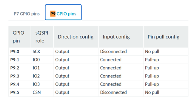
We need to control the GPIO LEDs from two cores (P9.00, P9.01 on the APP core and P9.02, P9.03 on the RAD core), i.e. on the same port - does this mean that the GPIO drivers on the cores must use the same memory?
Here are the "overlapping" visualizations that indicate possible conflicts when all LED control is enabled on both cores.
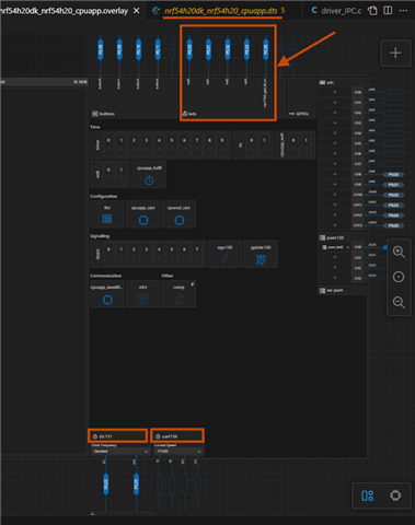
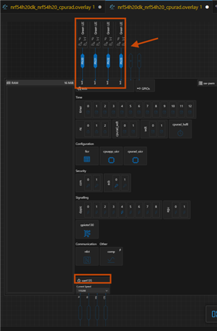
Is this possible? If so, how do I need to configure the "overlay" and prj.conf files for both cores?
Br, KeySoft