Jitter in high priority thread loop with irq_lock and k_sched_lock

I've been working on a custom device utilising the nRF52832 that needs to switch GPIOs in tightly controlled pulses. The problematic section is part of a much larger project written using nRF Connect SDK v2.6.1:

k_sched_lock();
key = irq_lock();
positive_electrodes();
k_busy_wait(50);

float_electrodes();
k_busy_wait(40);

negative_electrodes();
k_busy_wait(50);

ground_electrodes();
irq_unlock(key);
k_sched_unlock();   

k_usleep(10e3);

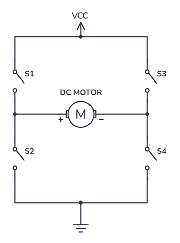
The code block is the body of an infinite while loop in a thread function. The thread priority is 1 (higher than every other created thread). The positive_electrodes, float_electrodes, negative_electrodes, and ground_electrodes functions are just wrappers around a series of log and gpio_pin_set_dt statements.

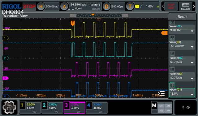
I am checking the GPIO waveforms on an oscilloscope, I would expect to see pulses that are 50us and 40us long. This is mostly what I see, however, every other second or so, I see a jump on the pulse width with a maximum of 190us when it should be 50us.

Pulse width jitter has been a major problem in previous versions of my software, that I drastically reduced by utilising k_busy_wait instead of k_usleep, and by adding the irq_lock. However, the jitter has not disappeared. Based on a sample size of 1000 pulses, the deviation for each of the 50us pulses I am scoping is about 10us, which is a lot higher than I would expect. 

Does anyone have any ideas of what could be causing the occasional extremely long pulses despite all the mitigation I have tried (irq_lock, k_sched_lock, highest priority thread)? I have tried moving from the thread based implementation to a chain of timers that start the next one on expiry but that just exacerbated the jitter beyond reason. 

Edit: I forgot to mention that while I extensively use the logging module, logging is turned off in the project config file since we have to way of interfacing with the MCU once in production.

Parents
  • Was there a reason to not just use hardware PWM to drive the GPIO? The pulses would then have no jitter; if code is required for each part of the pulse or some parts of the pulse the EGU could be used to generate interrupts which would handle any semaphores and the like; no need for thread interaction for the actual pulse timing.

    Maybe share the driving circuit for the electrodes; a 4-output PWM can control the Pos-Float-neg-ground phases by selectively setting each of the 4 outputs to (say) H1D0, D1D0, H0D1, H1D0 but need to see how the outputs are driven to confirm. It is possible to use more than one PWM synchronously with 0nSec phase delay as well as no jitter. I provide an example here; the nRF52832 is simple but the changed PWM implementation on the nRF52833 required slightly different code: pwm-anomaly-nrf52832-vs-nrf52833 and start-pwms-synchronous

  • The driving circuit is an H-bridge (I've pasted a dummy setup I found online; my circuit does not connect to a motor). I have 4 GPIOs going to the 4 switch inputs on the H-bridge arms. These signals have line buffers to avoid overloading the GPIOs.

    So when I call positive_electrodes(), S1 and S4 turn on. Similarly, when I call ground_electrodes(), S2 and S4 are turned on. I used 50us and 10ms times as examples in the code excerpt but I actually need to configure pulse widths between 50us - 500us delivered at 10Hz - 200Hz at runtime based on user input. 

    My initial idea when developing this system was to use PWM, but two channels are spoken for already. Plus, I needed the positive and negative pulses to be delivered successively with no overlap. As far as I know there aren't ways to implement a phase delay between two pins on the same PWM channel (at least in the NCS Zephyr APIs that I've checked). 

    Thanks for linking those threads, I took a look and they definitely are interesting. I haven't interacted with the PPI or EGU so I'll do some homework to see if those could imply a solution. Thanks!

  • Only 2 pins are required to drive the H-bridge (1 for S1,4 and 1 for S2,3), and the most important issue is usually to ensure that there is a way to control the dead band (non-overlap) as the drive voltages are not square waves as shown on (say) a logic analyser but instead exponential or linear ramps on both rising and falling edges. Overlap due to thresholds and sloping signals crossing can be catastrophic (shorted motor drivers exploding) or simply a nuisance (unwanted battery power loss). Here are some examples I provided for H-Bridge PWM with dead-bands; might be helpful:

    pwm-interrupts

    how-to-set-up-pwm-dead-time-at-the-end-of-period

Reply Children
No Data
Related