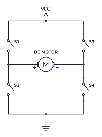
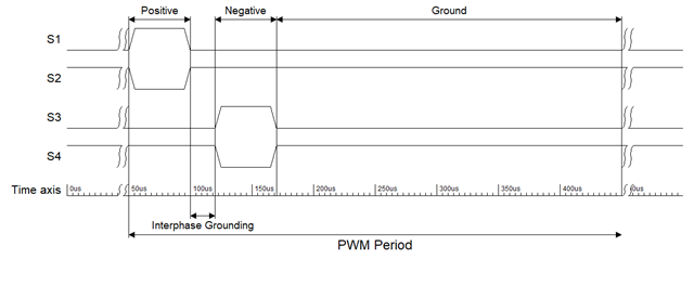
I've been working on a custom device utilising the nRF52832 that needs to switch GPIOs in tightly controlled pulses. The problematic section is part of a much larger project written using nRF Connect SDK v2.6.1:
k_sched_lock();
key = irq_lock();
positive_electrodes();
k_busy_wait(50);

float_electrodes();
k_busy_wait(40);

negative_electrodes();
k_busy_wait(50);

ground_electrodes();
irq_unlock(key);
k_sched_unlock();

k_usleep(10e3);
The code block is the body of an infinite while loop in a thread function. The thread priority is 1 (higher than every other created thread). The positive_electrodes, float_electrodes, negative_electrodes, and ground_electrodes functions are just wrappers around a series of log and gpio_pin_set_dt statements.
I am checking the GPIO waveforms on an oscilloscope, I would expect to see pulses that are 50us and 40us long. This is mostly what I see, however, every other second or so, I see a jump on the pulse width with a maximum of 190us when it should be 50us.
Pulse width jitter has been a major problem in previous versions of my software, that I drastically reduced by utilising k_busy_wait instead of k_usleep, and by adding the irq_lock. However, the jitter has not disappeared. Based on a sample size of 1000 pulses, the deviation for each of the 50us pulses I am scoping is about 10us, which is a lot higher than I would expect.
Does anyone have any ideas of what could be causing the occasional extremely long pulses despite all the mitigation I have tried (irq_lock, k_sched_lock, highest priority thread)? I have tried moving from the thread based implementation to a chain of timers that start the next one on expiry but that just exacerbated the jitter beyond reason.
Edit: I forgot to mention that while I extensively use the logging module, logging is turned off in the project config file since we have to way of interfacing with the MCU once in production.


