System On idle current v supply voltage issue/question

I've got a custom board fitted with an nRF52832.  Am running NCS v2.6.0.  Operation involves:

1. Being in System On idle with all peripherals disabled to keep current to a minimum.  Spends most of its time in this state

2. Gets "woken up" either by a GPIO trigger, or a k_timer() trigger.

That all functions as expected, and I'm just looking at current draw in the two different states using my PPK2, so I can get an idea of battery life.  Thing is, I am getting WILDLY different results (relatively speaking) based on the supply voltage I set within the Power Profiler.

Here are three screen shots of it in idle mode.

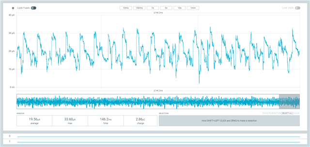
The first is with the voltage set to 3100mV (represents a fully charged battery in our application).  Average current is nearly 20uA, and shows significant spikes of activity about every ~ 7msec.

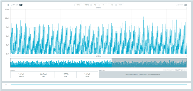
The second is with the voltage set to 2900mV, which represents a slightly discharged battery.  Average current is now down around 5uA

The third is with the voltage set to 2000mV.  This is basically a fully flat battery, but the nRF52 will happily work at this level (its spec'd down to 1.8V I believe)

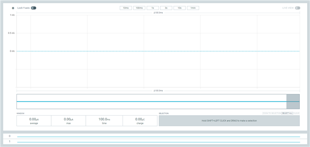
From the looks of this, the idle current is basically 0nA!!

I've done these measurements with the PPK2 both as a Source meter, and set the voltage levels within the Power Profiler, as well as with an external (variable) voltage source, with the PPK2 set up in Ampere meter mode.  And the results are basically the same. I can confirm my device is actually coming out of System On idle, as I can see the larger current draw during this mode, and I can see it appear when I do a scan with my Bluetooth sniffer.

My question is - is the nRF52832 idle current THAT sensitive to VDD level?  From the looks of it, operating it at VDD > 3.0V draws much more current that operating it at VDD = 2.8V.

And if that is the case, any explanation as to why?

The input voltage doesn't seem to have any real impact on the current during normal operation.

Cheers,

Mike

Parents
  • Hello,

    These plots look a bit unexpected. I suspect you have not connected the PPK correctly. Can you please share some information on how you have connected it? 

    Best regards,

    Edvin

  • Hi Edvin,

    In SOURCE mode, I have:

    • VOUT (PPK2) > VDD (Custom Board)
    • GND (PPK2) > GND (Custom Board)

    And in AMPERE mode, I have:

    • PSU(+) > VIN (PPK2)
    • PSU(-) > GND (PPK2)
    • VOUT (PPK2) > VDD (Custom Board)
    • GND (PPK2) > GND (Custom Board)

    I have just tested my custom hardware using a Current Ranger unit, just to check that it's not the PPK2 unit misbehaving. The Current Ranger seems to be giving more believable results - around 9uA at 3V and 6uA at 2V

    So, I'm either doing something wrong with how I'm connecting and configuring the PPK2, or my PPK2 is damaged.

    Cheers,

    Mike

  • ".. it's not the PPK2 unit misbehaving .."

    This is likely caused by the nRF52832 internal regulator being in Hysteretic Mode, which optimises current drain at very low currents and the user has no real control over this - except in the hardware design. Hysteretic Mode is where a periodic pulse of the internal regulator charges the external bulk capacitance between a low and a high threshold (aka bang-bang or on-off); the timing of this charge cycle is affected by the value and type of external bulk capacitors fitted and of course depends heavily on VDD supply voltage. The PPK2 is effectively aliasing between this VDD-dependent charge pulse and the PPK2 internal nRF52840 SAADC sample rate. A true multimeter would be less affected. Here are a few discussions related:

    depending-on-the-nrf52832-supply-voltage-can-the-quiescent-current-vary

    nrf52833-standby-current-reaches-60ua

    power-profiler-2-reported-power-increases-substantially-as-input-capacitance-is-increased

    high-current-in-idle

  •   

    Thanks for that info.

    I had a more detailed look at the output of my Current Ranger, and I can quite clearly see the current pulses I'd expect of a system giving short bursts of charge current to my bulk capacitance - they appear as 100uA peak, ~ 10usec wide, exponentially decaying pulses that repeat about every 10msec. That was measured at 3V.

    If I crunch those numbers, I get an average current during idle of about 10uA, which aligns with the display on my Current Ranger (my PPK2 is indicating about 20uA).

    I was under the impression the SAADC can sample at up to 200ksps. So, sampling every 5usec. I can see that it might well miss a 10usec wide pulse. Or those pulses might well be even shorter duration at lower input voltages - I'll have to take a look in more detail.

    Potted summary - the PPK2 isn't really the tool of choice for low current measurements.

    Cheers,

    Mike

Reply
  •   

    Thanks for that info.

    I had a more detailed look at the output of my Current Ranger, and I can quite clearly see the current pulses I'd expect of a system giving short bursts of charge current to my bulk capacitance - they appear as 100uA peak, ~ 10usec wide, exponentially decaying pulses that repeat about every 10msec. That was measured at 3V.

    If I crunch those numbers, I get an average current during idle of about 10uA, which aligns with the display on my Current Ranger (my PPK2 is indicating about 20uA).

    I was under the impression the SAADC can sample at up to 200ksps. So, sampling every 5usec. I can see that it might well miss a 10usec wide pulse. Or those pulses might well be even shorter duration at lower input voltages - I'll have to take a look in more detail.

    Potted summary - the PPK2 isn't really the tool of choice for low current measurements.

    Cheers,

    Mike

Children
No Data
Related