Real-Time Requirements | EasyDMA

Hello Nordic,

I am developing for a project that requires real-time accuracy. We are using ncs v2.9.1 Zephyr, an nRF54L15 and an IMU (w/ SPI interface) to acquire positional data. 

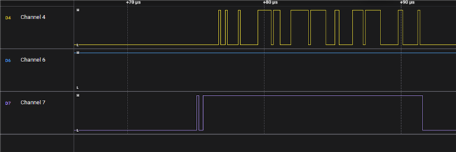
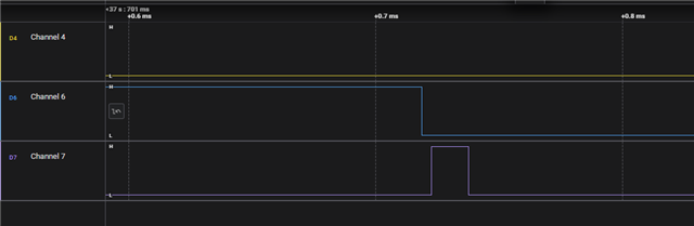
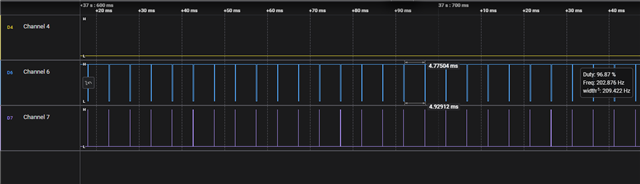
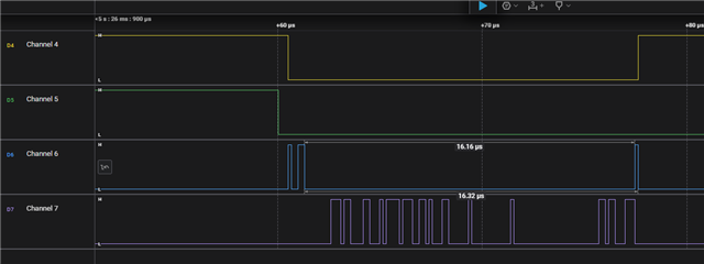
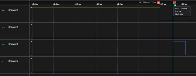
An observed issue is that we cannot reliably sample our IMU during BLE communications due to BLE interrupts. The interrupts prevent our main CPU thread and block us from calling spi_transceive_dt(). Because the IMU is tracking real-time data, any missed communications with the IMU cause significant accuracy loss in our system.

In theory, this should be solvable if we can use the DMA to cyclically service and buffer IMU communications. From the examples on the forum, I have found no other posts that contain this use case and as such no suitable answers. From my understanding the SPI peripheral is intrinsically using EasyDMA, but I cannot tell how to take advantage of this. Is it assumed while calling spi_transceive_dt() other threads can be run during this function call? If so, is there a way to schedule a SPI transceive that will not get interrupted by Bluetooth communication? 

Is this problem solvable using EasyDMA or otherwise?

Thank you,
Levi

Parents
  • Hello,

    At what speed/rate are you reading the IMU? And how many readings are you missing due to BLE events?

    If you want to look into DMA, you can have a look at this ticket, which discusses this:

     NRF54L15DK unable to use NRFX_SPIM_FLAG_TX_POSTINC flag in nrfx_spim_xfer API 

    Alternatively, there is an option to use PPI (Programmable peripheral interface). This way, you can connect events in one peripheral to a task in another. In your case, you would typipcally connect a timer event to the PPI, and you can trigger a transceive command from there.

    As an example, you can look at how the sample found in NCS\modules\hal\nordic\nrfx\samples\src\nrfx_ppi

    This uses a timer to toggle a GPIO, but you can replace the GPIO with any peripheral.

    You can see that this sample uses nrfx_giote_out_task_address_get() to find the address of the task in the GPIO. The equivavalent function for SPI is found in ncs\modules\hal\nordic\nrfx\drivers\include\nrfx_spim.h. Search for "address_get(" in that file, and you should find the ones that you need.

    Best regards,

    Edvin

  • Hi Edvin,

    Thanks for your response. The IMU is being sampled every 5ms and for missed readings, this can vary. Depending on the connection quality, we have missed over 100ms of data. Losing 1-2 samples can be impactful to our system accuracy.

    Thank you for your suggestion about the PPI as a solution. I agree it appears to have the functionality required. I will be traveling for business this next week, so I am unable to test my code. I will provide an update for other visitors of this thread and will fully respond late next week. 

    Looking over the example you suggested, I have found the functions you described:

    nrfx_spim_start_task_address_get()
    nrfx_spim_end_event_address_get()
    For the first function, I have the following code which links the timer to the SPI peripheral using the GPPI channel.
    nrfx_gppi_channel_endpoints_setup(gppiChannel, 
            nrfx_timer_compare_event_address_get(&timerDev, NRF_TIMER_CC_CHANNEL0),
            nrfx_spim_start_task_address_get(&spiDev));
    For the second function, the documentation suggests that you can use it to determine the number of events but does not go into detail. I am assuming you can calculate a delta?
    printk("Address Difference %d \n", nrfx_spim_end_event_address_get(&spiDev) - 
        nrfx_spim_start_task_address_get(&spiDev));
    The last puzzle piece is setting up the cyclical SPI transfer. The nrfx_spim_xfer() documentation goes into great detail which is nice. 
    static void prepareSPITransfer() {
        nrfx_err_t err;
        // Setup Buffer for Transfers
        nrfx_spim_xfer_desc_t spiTransferBuffer = NRFX_SPIM_XFER_TRX(txBuffer, sizeof(txBuffer), 
                                                                     rxBuffer, sizeof(rxBuffer));
        
        // Setup the Following Flags
        // NRFX_SPIM_FLAG_RX_POSTINC - Increments RX buffer address after transceive. Allows for repeated reads w/ same buf
        // NRFX_SPIM_FLAG_NO_XFER_EVT_HANDLER - Does not trigger an interrupt after transfer.
        // NRFX_SPIM_FLAG_HOLD_XFER - Sets up the transceive, but doesn't actually perform the transceive.
        // NRFX_SPIM_FLAG_REPEATED_XFER - Prepares for multiple transceives.
        uint32_t spiFlags = NRFX_SPIM_FLAG_RX_POSTINC | NRFX_SPIM_FLAG_NO_XFER_EVT_HANDLER | 
                            NRFX_SPIM_FLAG_HOLD_XFER | NRFX_SPIM_FLAG_REPEATED_XFER;
        
        // Setup Transfer
        err = nrfx_spim_xfer(&spiDev, &spiTransferBuffer, spiFlags);
        printk("SPIM Tansfer: %s\n", (err == NRFX_SUCCESS) ? "setup" : "not setup");
    }
    Most of the setup seems to be in the flags and how they operate. 

    All other code seems to be copy/paste from the GPIOTE example you suggested.

    Regards,

    Levi

  • Hello Edvin,

    I have made progress in implementing this interface, but found some confusing behavior. First when looking into the nrfx_spim.h file, for NRFX_SPIM_FLAG_HOLD_XFER, it states "Chip select must be configured to @ref NRF_SPIM_PIN_NOT_CONNECTED and managed outside the driver." What does this mean? Am I expected to setup a GPIO to also be triggered via GPPI for my SPI driver separately.

    Second, I was able to setup the GPPI interface correctly, but I am using GPIOTE instead of the timer. Our IMUs have an interrupt line which are triggered cyclically, so it serves the same purpose. The problem I am having is that when I try to schedule a repeated transfer to be used on each GPIOTE interrupt, the full SPI MOSI transmission is not being sent. Any ideas?

    Here are some waveforms:

    Channel 4 (Yellow): SPI MISO

    Channel 6 (Blue): IMU Interrupt Line

    Channel 7 (Purple): SPI MOSI

    (Previous) Healthy SPI Communication (Polled) with No Interrupts 

    (Current) IMU Interrupt GPIOTE Triggered SPI Communication  

    From above, it seems my GPIOTE linkage with the GPPI interface is working: every IMU interrupt is followed by an attempted SPI transmission. The SPI transmission is only a high for a few moments, and then low. It should be sending the value 0x8C = 0b1000 1100. See code below:

    static void setupSPITrigger() {
        // Prepare Configuration
        // Note: SPI CS is Floating for Repeated Automatic Transfer
        nrfx_spim_config_t spiConfig = {
            .sck_pin = SPI_CLK_PIN_201,
            .mosi_pin = SPI_MOSI_PIN_202,
            .miso_pin = SPI_MISO_PIN_204,
            .ss_pin = NRF_SPIM_PIN_NOT_CONNECTED,
            .ss_active_high = false,
            .irq_priority = NRFX_SPIM_DEFAULT_CONFIG_IRQ_PRIORITY,
            .orc = 0xFF,
            .frequency = NRFX_MHZ_TO_HZ(8),
            .mode = NRF_SPIM_MODE_0,
            .bit_order = NRF_SPIM_BIT_ORDER_MSB_FIRST,
            .miso_pull = NRF_GPIO_PIN_NOPULL,
            .ss_duration = 5UL,
            .dcx_pin = NRF_SPIM_PIN_NOT_CONNECTED,
            .use_hw_ss = false,  // TODO LR: Not sure if this should be true
            .rx_delay = 2UL,
        };
    
        // Perform Reconfigure
        nrfx_err_t err = nrfx_spim_reconfigure(&spiDev, &spiConfig);
        if (err != NRFX_SUCCESS) {
            printk("[SPI] FAILURE: Reconfiguration Failed\n");
            uPbit.SPI = FAIL;
            return;
        }
    
        // Setup Buffer for Transfers
        txBuffer[0] = (uint8_t)(0x0C | 0x80);
        nrfx_spim_xfer_desc_t spiTransferBuffer = NRFX_SPIM_XFER_TRX(txBuffer, 1,
                                                                     rxBuffer, 17);
    
        // Setup the Following Flags
        // NRFX_SPIM_FLAG_RX_POSTINC - Increments RX buffer address after transceive. Allows for repeated reads w/ same buf
        // NRFX_SPIM_FLAG_NO_XFER_EVT_HANDLER - Does not trigger an interrupt after transfer.
        // NRFX_SPIM_FLAG_HOLD_XFER - Sets up the transceive, but doesn't actually perform the transceive.
        // NRFX_SPIM_FLAG_REPEATED_XFER - Prepares for multiple transceives.
        uint32_t spiFlags = NRFX_SPIM_FLAG_RX_POSTINC | NRFX_SPIM_FLAG_NO_XFER_EVT_HANDLER |
                            NRFX_SPIM_FLAG_HOLD_XFER | NRFX_SPIM_FLAG_REPEATED_XFER;
    
        // Setup Transfer
        err = nrfx_spim_xfer(&spiDev, &spiTransferBuffer, spiFlags);
        if (err != NRFX_SUCCESS) {
            printk("[SPI] FAILURE: Transfer Setup Failed\n");
            uPbit.SPI = FAIL;
            return;
        }
    
        printk("[SPI] NRFX SPIM Setup for Repeated Transfer");
    }

    /********************************************************************************************/  /**
     *  <!-- Function Name: XXXX()  -->
     *  @brief
     *
     *************************************************************************************************/
    static void setupGPIOTE() {
        nrfx_err_t err;
    	uint8_t imuGPIOChannel;
    
    	// /* Connect GPIOTE instance IRQ to irq handler */
    	// IRQ_CONNECT(DT_IRQN(GPIOTE_NODE), DT_IRQ(GPIOTE_NODE, priority), nrfx_isr,
    	// 	    NRFX_CONCAT(nrfx_gpiote_, GPIOTE_INST, _irq_handler), 0);
    
    	/* Initialize GPIOTE (the interrupt priority passed as the parameter
    	 * here is ignored, see nrfx_glue.h).
    	 */
        // Initialize GPIOTE
        // NRFX_GPIOTE_DEFAULT_CONFIG_IRQ_PRIORITY
    	err = nrfx_gpiote_init(&gpioteDev, 0);
    	if (err != NRFX_SUCCESS && err != NRFX_ERROR_ALREADY) {
    		printk("nrfx_gpiote_init error: 0x%08X", err);
    		return;
    	}
    
    	err = nrfx_gpiote_channel_alloc(&gpioteDev, &imuGPIOChannel);
    	if (err != NRFX_SUCCESS) {
    		printk("Failed to allocate in_channel, error: 0x%08X", err);
    		return;
    	}
    
    	/* Initialize input pin to generate event on high to low transition
    	 * (falling edge) and call button_handler()
    	 */
    	static const nrf_gpio_pin_pull_t gpioPinConfig = NRF_GPIO_PIN_PULLUP;
    	nrfx_gpiote_trigger_config_t triggerConfig = {
    		.trigger = NRFX_GPIOTE_TRIGGER_HITOLO,
    		.p_in_channel = &imuGPIOChannel,
    	};
    	nrfx_gpiote_input_pin_config_t gpioteConfig = {
    		.p_pull_config = &gpioPinConfig,
    		.p_trigger_config = &triggerConfig,
    		.p_handler_config = NULL,
    	};
    
    	err = nrfx_gpiote_input_configure(&gpioteDev, GPIO_IMU_PIN, &gpioteConfig);
    	if (err != NRFX_SUCCESS) {
    		printk("nrfx_gpiote_input_configure error: 0x%08X", err);
    		return ;
    	}
    }
    
    /********************************************************************************************/  /**
     *  <!-- Function Name: XXXX()  -->
     *  @brief
     *
     *************************************************************************************************/
    static void setupGPPI() {
        nrfx_err_t err;
        uint8_t gppiChannel;
    
        // Allocate GPPI Channel
        err = nrfx_gppi_channel_alloc(&gppiChannel);
        printk("[SPI] NRFX GPPI Channel: %s\n", (err == NRFX_SUCCESS) ? "initialized" : "not initialized");
    
        // Connect GPIOTE to SPI Event Task
        nrfx_gppi_channel_endpoints_setup(gppiChannel,
    		nrfx_gpiote_in_event_address_get(&gpioteDev, GPIO_IMU_PIN),
    		nrfx_spim_start_task_address_get(&spiDev));
    
        // Enable GPPI Channel
        nrfx_gppi_channels_enable(BIT(gppiChannel));
        nrfx_gpiote_trigger_enable(&gpioteDev, GPIO_IMU_PIN, true);
    }
    

  • Here is a zoomed out picture of the GPIOTE working with SPI. 

  • Update on this, I realized that my logic analyzer was sampling at 6.25 Mb/s while the SPI bus is operating at 8MHz, so the communication is fine. The logic displayer was just aliasing data. At the moment, I have most of the driver working with the following two GPPI pipelines.

    GPIOTE --> GPPI --> SPI Transfer   

    then     

    SPI End Event --> GPPI --> Timer (Counter) --> Interrupt (Reset DMA List Rx Buffer Pointer)

    Despite the above, I am still unsure how the chip select is intended to be setup for this. The header file cryptically states that it must be handled outside the driver... Are we intended to use the fork functionality to trigger a GPIO low whenever we intend to perform a SPI Transfer?

    Additionally, I found a few interesting forum posts that stated there is no way for the SPI Transfer from GPPI to know when the DMA List (which is what is being used underneath) is full. As such, the DMA list's Rx Buffer must be regularly serviced otherwise a crash WILL occur. I find this to be very odd design... My intent with this feature overall was to mitigate data loss during Bluetooth disconnections which I believe to be as long as 5 seconds. 

    Pondering this scenario, for the data collected, there are 17 bytes of data sampled at 200Hz for 5 seconds. This means for a buffer to not fill up during one of these disconnections we would need:

    17bytes * 200Hz *  5 seconds = 17,000 byte

    Moreover, to use the data in the buffers, it seems most convenient to double buffer all the data versus ring the buffer. Ringing the buffer poses the risk of overflow if a Bluetooth interrupt occurs that blocks the processor from ringing the buffer and thus, the DMA list overruns the buffer it is selected...

    So, double buffering requires twice the amount of bytes: 34,000 ~= 34kB.

    From my pipeline, the last step (the counter interrupt) is intended to reset the buffer as quickly possible once the processor is no longer blocked by Bluetooth interrupts. The device overflowing its memory and crashing is not tolerable in my application.

    None of this seems to be clearly documented, so I am piecing together what I can from forum posts. Is this the intended way for these peripherals to function?

  • For the CSN pin this can't be controlled by GPPI. Do you have any other devices on the SPI bus? Is it an alternative to just set it before you start your 5 second routine, and then unset it after it is done?

    Best regards,

    Edvin

  • Hi Edvin,


    The bus is serviced every 5ms, so setting and unsetting manually is not ideal.

    It looks like you can set multiple channels from the same event. I was thinking of the following:

    First,

    IMU Interrupt (GPIOTE)  ---> GPPI Channel --->  SPI Transmission Start

                                           ----> GPPI Channel ---> Chip Select High-to-Low (GPIOTE)

    Then,

    SPI Transmission End ----> GPPI Channel ---> Chip Select Low-to-High (GPIOTE)


    Would this work reliably?                

Reply
  • Hi Edvin,


    The bus is serviced every 5ms, so setting and unsetting manually is not ideal.

    It looks like you can set multiple channels from the same event. I was thinking of the following:

    First,

    IMU Interrupt (GPIOTE)  ---> GPPI Channel --->  SPI Transmission Start

                                           ----> GPPI Channel ---> Chip Select High-to-Low (GPIOTE)

    Then,

    SPI Transmission End ----> GPPI Channel ---> Chip Select Low-to-High (GPIOTE)


    Would this work reliably?                

Children
  • That is up to you to test. The last one (hooked on the SPI Transmission End) is fine. The question is whether or not it is enough to set the CSN pin at the same time as you start the transmission. Is it enough for the SPI slave to react to it? Does it behave the way you want when you do it this way?

    If not, you probably need to set it a little bit sooner. Perhaps you need to include a timer, first set the CSN, start the timer, and when the timer reaches a certain value, then start the SPI transmission.

    Best regards,

    Edvin

  • Ok, thank you for the instruction.

    One final question: When testing the module, I did not do as the driver instructed. The driver states to leave "Chip select must be configured to @ref NRF_SPIM_PIN_NOT_CONNECTED and managed outside the driver."  Instead, I configured it to pin 69. See below.

    #define SPI_CLK_PIN_201      65
    #define SPI_MOSI_PIN_202     66
    #define SPI_MISO_PIN_204     68
    #define SPI_CS_PIN_205       69
    #define SPI_INSTANCE_IDX     00
    const nrfx_spim_t spiDev = NRFX_SPIM_INSTANCE(SPI_INSTANCE_IDX);
    
    nrfx_spim_config_t spiConfig = {
            .sck_pin = SPI_CLK_PIN_201,
            .mosi_pin = SPI_MOSI_PIN_202,
            .miso_pin = SPI_MISO_PIN_204,
            .ss_pin = SPI_CS_PIN_205,
            .ss_active_high = false,
            .irq_priority = NRFX_SPIM_DEFAULT_CONFIG_IRQ_PRIORITY,
            .orc = 0x00,
            .frequency = NRFX_MHZ_TO_HZ(8),
            .mode = NRF_SPIM_MODE_0,
            .bit_order = NRF_SPIM_BIT_ORDER_MSB_FIRST,
            .miso_pull = NRF_GPIO_PIN_NOPULL,
            .ss_duration = 5UL,
            .dcx_pin = NRF_SPIM_PIN_NOT_CONNECTED,
            .use_hw_ss = true,  // TODO LR: Not sure if this should be true
            .rx_delay = 2UL,
        };
    
        // Perform Reconfigure
        nrfx_err_t err = nrfx_spim_reconfigure(&spiDev, &spiConfig);
        if (err != NRFX_SUCCESS) {
            printk("[SPI] FAILURE: Reconfiguration Failed\n");
        }

    Despite this, the device seems to operate fine. When scoping the lines, the CS functions appropriately. Is there any consequence or negative side effect if I keep it this way? Why does this work?

    Channel 4 (Yellow) - SPI CS

    Channel 5 (Green) - IMU Interrupt

    Channel 6 (Blue) - SPI MOSI

    Channel 7 (Purple) - SPI MISO

  • I guess the SPIS device that you are using accepts that the CS pin is set at the same time as the MOSI starts outputting data. Some devices uses this as a wakeup source to trigger some task, and is not ready to receive data before a certain amount of time has passed. 

    How do you trigger the CS pin? Is it being done by the driver, or do you do it using the fork and PPI?

    BR,

    Edvin

  • Yes, that makes sense. my device only needs 40ns for CS setup/hold time. Upon closer inspection of the waveform there is a 60ns hold time.


    For my code, the CS is being trigger by the driver. Is the CS being triggered (almost) at the same time as the MOSI why the documentation states to handle the CS outside the driver? Can I leave it like this?

  • Ok, I thought you controlled it using PPI directly (PPI + GPIOTE), but it seems like the driver handles this, yes. 

    LeviRand said:
    The driver states to leave "Chip select must be configured to @ref NRF_SPIM_PIN_NOT_CONNECTED and managed outside the driver.

    I believe this snippet is coming from the older chips where the CSN was not hardware controlled, but controlled by the software drivers. At that point, the CSN pins could not be handled by the peripheral itself, and hence not controlled automatically by the PPI directly (unless you specify this as a separate task in PPI). 

    BR,
    Edvin

Related