Memfault OTA for multiple nRF boards (NCS 3.1.1)

Hello,

Im currently in the process of integrating Memfault OTA on the nRF9151 DK. My project has multiple boards: nRF9151 DK connects with nRF52840 DK via UART for communication. For OTA, I figured that I can use memfault OTA to update the nRF9151 DK because it supports out of the box. However, I'm not sure how to approach for nRF52840 DK. I know that since 2 boards connect using UART, I can put it into DFU mode and just do a serial recovery. From Memfault doc:

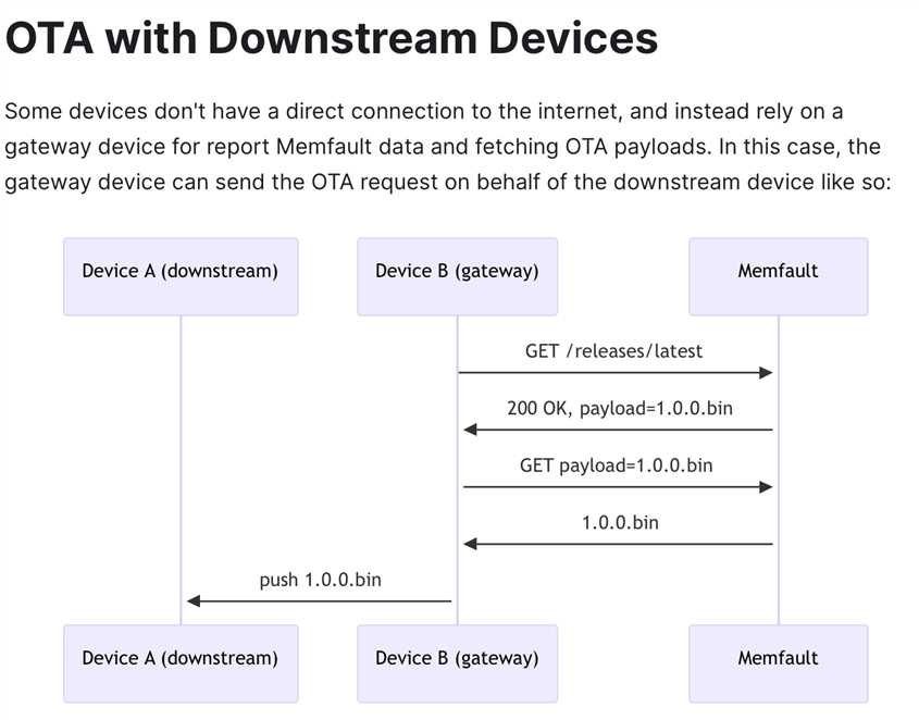
Or the doc recommends to bundle the update into 1 OTA:

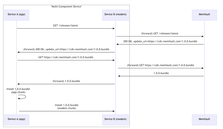
Since the nRF9151 DK has external flash, it has enough storage for this approach as well. But memfault guide http://mflt.io/nrf-fota-setup said to just call memfault_fota_start to start the OTA process. That works great for the nRF9151 DK, but what about the nRF52840 board I have connected? The document doesn't mention this very clear on how I could do the "get" and "push" for downstream board, or how I can do the "bundle" approach.

Even if I don't consider the nRF52840 DK, I still need to update both the app and the modem fw on the nRF9151 DK. Which function/API should I override? Or is there already an implementation? The only function I can override is the memfault_fota_download_callback, but this is called after everything is done. I just want to check if the payload is supposed to be for the nRF52840 DK board and save it in a different partition instead?

I'd appreciate the help. Thanks so much.

Parents
  • Hello, apologies for the late reply. 

    I have forwarded this question to our Memfault experts and hope to have an answer by end of tomorrow. Sorry for any inconvenience

    Kind regards,
    Øyvind

  • Thanks Øyvind,

    Hope to hear updates from you soon as I'm currently being feature-blocked by this.

  • Thanks for the question  ! This is a somewhat complicated feature, so bear with me-

    1. We recommend sending a custom update bundle (as you saw in the docs), however we don't currently have a built-in library for handling this scenario, so you'll have to generate your update bundle yourself, as part of the build process
    2. You'll need to enable `CONFIG_DFU_TARGET_CUSTOM=y`, and implement the custom dfu target handler functions (notably, make sure `dfu_target_custom_identify()` can identify the header in your bundle, i.e. put a magic string at the front of it):
      1. https://docs.nordicsemi.com/bundle/ncs-latest/page/nrf/libraries/dfu/dfu_target.html
      2. https://github.com/nrfconnect/sdk-nrf/blob/902e710b42aca9fc06a2a9d69a43cbb0e8465e80/include/dfu/dfu_target_custom.h
    3. To apply the downstream device update image, you'll want to use SMP over the serial port connection
      1. You'll need to enable serial SMP on the downstream device
      2. You'll want to include calls to `dfu_target_smp_*` functions inside your `dfu_target_custom` handlers, to properly execute the SMP update when processing the custom update: github.com/.../dfu_target_smp.h

    I'd recommend adding a lot of `LOG_INF` and `LOG_ERR` messages in your implementation, to make it easier to debug as you go.

    For a first implementation, you might just want to update the nrf91 only, by issuing the correct `dfu_target_mcuboot` calls from your custom DFU target implementation (accounting for the bundle header). Once that works, you can move on to implementing the SMP target.

    Let me know if you have any questions as you work on the implementation Pray

    Thanks!
    Noah

  • Hi Noah,

    Thank you for your response. I got the nrf91 only part working. But now I got stuck at the smp part.

    Currently I'm using 1 uart instance. nrf91 uses UART2 and nrf52 uses uart1. All are async uart.

    Before enable download, I have in my custom dfu target function to put nrf52 into serial recovery, and disable uart2 on the nrf91 before calling smp init with the hope that it'll release the uart for smp to use.

    However, my smp client init failed with err 3.

    err = dfu_target_smp_client_init();
    if (err) {
    LOG_ERR("Failed to init smp dfu target: %d", err);
    }

    <err> nRF9151: Failed to init smp dfu target: 3

    Error code 3 for mcumgr is just a generic invalid value error.

    Here is my prj.conf for your reference, I only included relevant config here because my config is quite long:

    CONFIG_MEMFAULT_FOTA=y
    
    # Enable testing FOTA via a CLI command
    # CONFIG_MEMFAULT_FOTA_CLI_CMD=y
    
    # The subsystems we need so OTA payloads can be written to
    # flash and updated by MCUBoot
    CONFIG_MCUBOOT_IMG_MANAGER=y
    CONFIG_DFU_TARGET=y
    CONFIG_DFU_TARGET_MCUBOOT=y
    CONFIG_DFU_TARGET_SMP=y
    CONFIG_DFU_TARGET_CUSTOM=y
    CONFIG_IMG_MANAGER=y
    CONFIG_FLASH=y
    CONFIG_FLASH_MAP=y
    CONFIG_STREAM_FLASH=y
    CONFIG_IMG_ERASE_PROGRESSIVELY=y
    
    # For Memfault FOTA, we will use the FOTA_DOWNLOAD API's
    # from the nRF Connect SDK which depends on the DOWNLOADER
    CONFIG_FOTA_DOWNLOAD=y
    CONFIG_DOWNLOADER=y
    CONFIG_DOWNLOADER_MAX_FILENAME_SIZE=400
    CONFIG_DOWNLOADER_STACK_SIZE=1600
    
    # Enable printing of file download progress to console
    CONFIG_FOTA_DOWNLOAD_PROGRESS_EVT=y
    
    CONFIG_FOTA_PERIODIC_CHECK_INTERVAL_SECS=120
    
    # SMP Client dependencies
    CONFIG_ZCBOR=y
    CONFIG_MCUMGR=y
    CONFIG_SMP_CLIENT=y
    CONFIG_MCUMGR_GRP_IMG_CLIENT=y
    CONFIG_MCUMGR_GRP_OS_CLIENT=y
    CONFIG_MCUBOOT_BOOTUTIL_LIB=y
    
    # CONFIG_TFM_SECURE_UART=n
    # CONFIG_TFM_LOG_LEVEL_SILENCE=y
    
    CONFIG_BASE64=y
    CONFIG_CRC=y
    
    # UART
    CONFIG_SERIAL=y
    CONFIG_UART_ASYNC_API=y
    
    # UART use hardware counter instead
    CONFIG_UART_2_ASYNC=y
    CONFIG_UART_2_NRF_HW_ASYNC=y
    CONFIG_UART_2_NRF_HW_ASYNC_TIMER=2
    CONFIG_NRFX_TIMER2=y

    And here is the snippet I tried to init dfu_target_smp

    /* Helper function to open smp for the aux update */
    static int open_aux(uint32_t size) {
    	int err;
    
    	/* Activate it here because it deactivates the same uart as smp is using */
    	(void)activate_recovery_cb();
    	/* Enable smp but in recovery mode */
    	err = dfu_target_smp_recovery_mode_enable(dummy_recovery_cb);
    	if (err) {
    		LOG_ERR("Failed to enable smp recovery mode: %d", err);
    		return err;
    	}
    
    	err = dfu_target_smp_client_init();
    	if (err) {
    		LOG_ERR("Failed to init smp dfu target: %d", err);
    	}
    	return err;
    }

    In addition, this warning keeps showing up:

    warning: UART_2_ASYNC (defined at drivers/serial/Kconfig.nrfx_uart_instance:14) was assigned the
    value 'y' but got the value 'n'. Check these unsatisfied dependencies: (!UART_2_INTERRUPT_DRIVEN)
    (=n). See docs.zephyrproject.org/.../kconfig.html and/or look up
    UART_2_ASYNC in the menuconfig/guiconfig interface. The Application Development Primer, Setting
    Configuration Values, and Kconfig - Tips and Best Practices sections of the manual might be helpful
    too.

    I thought maybe because I use the same UART instance. So I tried to an overlay for uart0 and still got the same error every time I tried to build.

    My questions:

    1. Is it not possible to use 1 UART instance for both normal communication and smp?

    2. If it is possible, how would I do it (release uart device somehow?). If not, I think I need to use a different uart line right?

  • Hi  -

    You might find this sample a good reference, it implements an SMP DFU target on the nrf9160dk (which has an on-board nrf52 connected over UART):
    https://docs.nordicsemi.com/bundle/ncs-latest/page/nrf/samples/cellular/nrf_cloud_rest_fota/README.html#building_and_running

    You can find the relevant Kconfig settings referenced there and in the `smp_svr` sample reference.

    It's a little different, since it accepts 1 image at a time (i.e. APP, MODEM, SMP (nrf52 downstream mcuboot payload), but generally it will work similarly to your setup.

  • Thank you. I took a look at those. I was able to move past the warning.

    But when init, I encountered a SECURE FAULT because I'm sharing 1 serial line.

    I tried to use 2 UART lines this time.

    UART2 from nRF91 -> UART1 on nRF52 for normal communication.

    UART1 from nRF91 -> UART0 on nRF52 for SMP, respectively.

    When the check for OTA is available, and the dfu_target_smp tried to send an echo command to the nRF52, it failed. With hardware control lines connected, it just stuck waiting for the flow control lines to be asserted. I disabled it to check, and I was right, the echo command time out and failed.

    I verified that the nRF52 is actually in serial recovery because I have the LED1 enabled when it's in serial recovery.

    To verify that this is a uart issue, I also try to swap the UART1 and UART0 connection, so now UART2 -> UART0 on the nRF52 DK, and indeed the commands that normally works for UART1 now receives no response on UART0.

    Here is the overlay (I put these in both the boards and in mcuboot sysbuild):

    / {
        /* Tell Zephyr the retention region is used for boot-mode */
        chosen {
            /delete-property/ zephyr,shell-uart;
            /delete-property/ zephyr,bt-mon-uart;
            /delete-property/ zephyr,bt-c2h-uart;
    
            zephyr,boot-mode = &retention0;
            zephyr,uart-mcumgr = &uart0;
        };
    
        /* Retention region for boot mode */
        sram@2003FC00 {
    		compatible = "zephyr,memory-region", "mmio-sram";
    		reg = <0x2003FC00 DT_SIZE_K(1)>;
    		zephyr,memory-region = "RetainedMem";
    		status = "okay";
    
    		retainedmem {
    			compatible = "zephyr,retained-ram";
    			status = "okay";
    			#address-cells = <1>;
    			#size-cells = <1>;
    
    			retention0: boot_mode@0 {
    				compatible = "zephyr,retention";
    				status = "okay";
    				reg = <0x0 0x100>;
    				prefix = [08 04];
    				checksum = <1>;
    			};
    		};
        };
    };
    
    &gpio0 {
            status = "okay";
    };
    
    &gpio1 {
            status = "okay";
    };
    
    &gpiote0 {
            status = "okay";
    };
    
    &nrf_radio_fem_spi {
        status = "disabled";
    };
    
    &pinctrl {
        uart0_default_custom: uart0_default_custom {
            group1 {
                psels = <NRF_PSEL(UART_TX, 1, 2)>,
                    <NRF_PSEL(UART_RTS, 1, 1)>;
            };
            group2 {
                psels = <NRF_PSEL(UART_RX, 1, 4)>,
                    <NRF_PSEL(UART_CTS, 1, 3)>;
                bias-pull-up;
            };
        };
    
        uart0_sleep_custom: uart0_sleep_custom {
            group1 {
                psels = <NRF_PSEL(UART_TX, 1, 2)>,
                    <NRF_PSEL(UART_RX, 1, 4)>,
                    <NRF_PSEL(UART_RTS, 1, 1)>,
                    <NRF_PSEL(UART_CTS, 1, 3)>;
                low-power-enable;
            };
        };
    
        uart1_default_custom: uart1_default_custom {
            group1 {
                psels = <NRF_PSEL(UART_TX, 0, 29)>,
                    <NRF_PSEL(UART_RTS, 0, 28)>;
            };
            group2 {
                psels = <NRF_PSEL(UART_RX, 0, 31)>,
                    <NRF_PSEL(UART_CTS, 0, 30)>;
                bias-pull-up;
            };
        };
    
        uart1_sleep_custom: uart1_sleep_custom {
            group1 {
                psels = <NRF_PSEL(UART_TX, 0, 29)>,
                    <NRF_PSEL(UART_RX, 0, 31)>,
                    <NRF_PSEL(UART_RTS, 0, 28)>,
                    <NRF_PSEL(UART_CTS, 0, 30)>;
                low-power-enable;
            };
        };
    };
    
    &uart0 {
        compatible = "nordic,nrf-uarte";
        status = "okay";
        current-speed = <115200>;
        pinctrl-0 = <&uart0_default_custom>;
        pinctrl-1 = <&uart0_sleep_custom>;
        pinctrl-names = "default", "sleep";
    };
    
    &uart1 {
        compatible = "nordic,nrf-uarte";
        status = "okay";
        hw-flow-control;
        current-speed = <115200>;
        pinctrl-0 = <&uart1_default_custom>;
        pinctrl-1 = <&uart1_sleep_custom>;
        pinctrl-names = "default", "sleep";
    };
    
    /* Reduce SRAM0 usage to account for non-init area */
    &sram0 {
        reg = <0x20000000 DT_SIZE_K(255)>;
    };

    I don't really know what I should do to make it work. I also attempted to cut solder bridge 50, 51, 52, 53 that connects UART0 to VCOM0, and it also doesn't work...

    I even change between ASYNC using DMA and Interrupt and none of it work. UART1 is working fine though. But not UART0 no matter what I did.

    CONFIG_UART_INTERRUPT_DRIVEN=y
    CONFIG_UART_0_ASYNC=n
    CONFIG_UART_0_INTERRUPT_DRIVEN=y

    I ran out of option and don't really know what to do.

  •   An update:

    The actual culprit is the UART1 port on the nRF9151. I found this thread with a related issue but for an nRF9160 DK and I was able to resolve the issue.

    To be transparent, after my hopeless attempt at enable UART1 and UART3 to work on the nRF9151, I gave up and just assigned `zephyr,uart-mcumgr` to uart0, swapped the console to uart3, and it worked.

    For me, uart1 makes sense because it was owned by secure domain. But uart3 just didn't work and I didn't know why, even with and without hardware control lines, it doesn't output anything although I enabled it with pins in the overlay.

    Here is my current working overlay for anyone who has the same issue as mine in the future:

    / {
    	chosen {
            zephyr,uart-mcumgr = &uart0;
            zephyr,console = &uart3;
            zephyr,shell-uart = &uart3;
        };
    };
    
    &gpio0 {
    		status = "okay";
    };
    
    &gpiote {
    		status = "okay";
    };
    
    &pinctrl {
    	uart2_default_custom: uart2_default_custom {
    		group1 {
    			psels = <NRF_PSEL(UART_TX, 0, 19)>,
    				<NRF_PSEL(UART_RTS, 0, 18)>;
    		};
    		group2 {
    			psels = <NRF_PSEL(UART_RX, 0, 17)>,
    				<NRF_PSEL(UART_CTS, 0, 16)>;
    			bias-pull-up;
    		};
    	};
    
    	uart2_sleep_custom: uart2_sleep_custom {
    		group1 {
    			psels = <NRF_PSEL(UART_TX, 0, 19)>,
    				<NRF_PSEL(UART_RX, 0, 17)>,
    				<NRF_PSEL(UART_RTS, 0, 18)>,
    				<NRF_PSEL(UART_CTS, 0, 16)>;
    			low-power-enable;
    		};
    	};
    
    	uart3_default_custom: uart3_default_custom {
    		group1 {
    			psels = <NRF_PSEL(UART_TX, 0, 3)>,
    				<NRF_PSEL(UART_RX, 0, 31)>;
    		};
    	};
    
    	uart3_sleep_custom: uart3_sleep_custom {
    		group1 {
    			psels = <NRF_PSEL(UART_TX, 0, 3)>,
    				<NRF_PSEL(UART_RX, 0, 31)>;
    		};
    	};
    };
    
    &i2c3 {
    	status = "disabled";
    };
    
    &i2c2 {
        status = "disabled";
    };
    
    &spi3 {
    	status = "disabled";
    };
    
    &pwm0 {
    	status = "disabled";
    };
    
    &pwm1 {
    	status = "disabled";
    };
    
    &pwm2 {
    	status = "disabled";
    };
    
    &pwm3 {
    	status = "disabled";
    };
    
    &uart2 {
    	compatible = "nordic,nrf-uarte";
    	status = "okay";
    	hw-flow-control;
    	current-speed = <115200>;
    	pinctrl-0 = <&uart2_default_custom>;
    	pinctrl-1 = <&uart2_sleep_custom>;
    	pinctrl-names = "default", "sleep";
    };
    
    &uart3 {
    	compatible = "nordic,nrf-uarte";
    	status = "okay";
    	current-speed = <115200>;
    	pinctrl-0 = <&uart3_default_custom>;
    	pinctrl-1 = <&uart3_sleep_custom>;
    	pinctrl-names = "default", "sleep";
    };
    
    &uart0 {
    	status = "okay";
    	hw-flow-control;
    };

    Of course this makes the log unavailable. Using RTT log with an onboard debugger somehow took control of the uart0 port (although I disabled vcom0 in the board configurator), so I had to use an external JLink probe.

    Anyway, I was able to get SMP to write update to my other device now.

    But at the end of the update, I encountered an error 

    <err> mcumgr_grp_img_client: Missing mandatory parametrs

    from this line, I tried to add more debug prints, as shown below:

    LOG_ERR("hash len %d, img mgmt data sha len %d version len %d slot found %d",
    hash.len, IMG_MGMT_DATA_SHA_LEN, version.len,
    zcbor_map_decode_bulk_key_found(list_res_decode,
    ARRAY_SIZE(list_res_decode),
    "slot"));

    <dbg> mcumgr_grp_img_client: hash len 0 != img mgmt data sha len 32, version len 5 slot found 1

    Is this concerning that the hash len = 0? I rebooted the device and seems like it works fine. So I'm unsure if I'm missing any steps in generating the image or if there's anything that I need to look into.

    I have this config enabled, not sure if it has anything to do with this:

    CONFIG_BOOT_SERIAL_IMG_GRP_HASH=y

    Any idea would be appreciated. Thank you for your patience with me.

Reply
  •   An update:

    The actual culprit is the UART1 port on the nRF9151. I found this thread with a related issue but for an nRF9160 DK and I was able to resolve the issue.

    To be transparent, after my hopeless attempt at enable UART1 and UART3 to work on the nRF9151, I gave up and just assigned `zephyr,uart-mcumgr` to uart0, swapped the console to uart3, and it worked.

    For me, uart1 makes sense because it was owned by secure domain. But uart3 just didn't work and I didn't know why, even with and without hardware control lines, it doesn't output anything although I enabled it with pins in the overlay.

    Here is my current working overlay for anyone who has the same issue as mine in the future:

    / {
    	chosen {
            zephyr,uart-mcumgr = &uart0;
            zephyr,console = &uart3;
            zephyr,shell-uart = &uart3;
        };
    };
    
    &gpio0 {
    		status = "okay";
    };
    
    &gpiote {
    		status = "okay";
    };
    
    &pinctrl {
    	uart2_default_custom: uart2_default_custom {
    		group1 {
    			psels = <NRF_PSEL(UART_TX, 0, 19)>,
    				<NRF_PSEL(UART_RTS, 0, 18)>;
    		};
    		group2 {
    			psels = <NRF_PSEL(UART_RX, 0, 17)>,
    				<NRF_PSEL(UART_CTS, 0, 16)>;
    			bias-pull-up;
    		};
    	};
    
    	uart2_sleep_custom: uart2_sleep_custom {
    		group1 {
    			psels = <NRF_PSEL(UART_TX, 0, 19)>,
    				<NRF_PSEL(UART_RX, 0, 17)>,
    				<NRF_PSEL(UART_RTS, 0, 18)>,
    				<NRF_PSEL(UART_CTS, 0, 16)>;
    			low-power-enable;
    		};
    	};
    
    	uart3_default_custom: uart3_default_custom {
    		group1 {
    			psels = <NRF_PSEL(UART_TX, 0, 3)>,
    				<NRF_PSEL(UART_RX, 0, 31)>;
    		};
    	};
    
    	uart3_sleep_custom: uart3_sleep_custom {
    		group1 {
    			psels = <NRF_PSEL(UART_TX, 0, 3)>,
    				<NRF_PSEL(UART_RX, 0, 31)>;
    		};
    	};
    };
    
    &i2c3 {
    	status = "disabled";
    };
    
    &i2c2 {
        status = "disabled";
    };
    
    &spi3 {
    	status = "disabled";
    };
    
    &pwm0 {
    	status = "disabled";
    };
    
    &pwm1 {
    	status = "disabled";
    };
    
    &pwm2 {
    	status = "disabled";
    };
    
    &pwm3 {
    	status = "disabled";
    };
    
    &uart2 {
    	compatible = "nordic,nrf-uarte";
    	status = "okay";
    	hw-flow-control;
    	current-speed = <115200>;
    	pinctrl-0 = <&uart2_default_custom>;
    	pinctrl-1 = <&uart2_sleep_custom>;
    	pinctrl-names = "default", "sleep";
    };
    
    &uart3 {
    	compatible = "nordic,nrf-uarte";
    	status = "okay";
    	current-speed = <115200>;
    	pinctrl-0 = <&uart3_default_custom>;
    	pinctrl-1 = <&uart3_sleep_custom>;
    	pinctrl-names = "default", "sleep";
    };
    
    &uart0 {
    	status = "okay";
    	hw-flow-control;
    };

    Of course this makes the log unavailable. Using RTT log with an onboard debugger somehow took control of the uart0 port (although I disabled vcom0 in the board configurator), so I had to use an external JLink probe.

    Anyway, I was able to get SMP to write update to my other device now.

    But at the end of the update, I encountered an error 

    <err> mcumgr_grp_img_client: Missing mandatory parametrs

    from this line, I tried to add more debug prints, as shown below:

    LOG_ERR("hash len %d, img mgmt data sha len %d version len %d slot found %d",
    hash.len, IMG_MGMT_DATA_SHA_LEN, version.len,
    zcbor_map_decode_bulk_key_found(list_res_decode,
    ARRAY_SIZE(list_res_decode),
    "slot"));

    <dbg> mcumgr_grp_img_client: hash len 0 != img mgmt data sha len 32, version len 5 slot found 1

    Is this concerning that the hash len = 0? I rebooted the device and seems like it works fine. So I'm unsure if I'm missing any steps in generating the image or if there's anything that I need to look into.

    I have this config enabled, not sure if it has anything to do with this:

    CONFIG_BOOT_SERIAL_IMG_GRP_HASH=y

    Any idea would be appreciated. Thank you for your patience with me.

Children
  • Hello, just the final update. I tried to follow this thread to get hash working, but some reason the read back hash always has len = 0, although I use mcuboot imgtool.py to check for the hash info (and it is there with len = 32 - SHA256).

    I decided to switch nRF52 to running SMP server with dual slots because I felt like having it as single slot is quite risky for remote deployment.

    I was able to get the OTA bundle working with Memfault! Thank you so much  for your recommendation and resources. Much appreciated!

  • Hi  -

    I'm glad to hear it- that was my suggestion, to use `imgtool` to check the binary file. Dual slots is a good idea for resiliency (you will need the fallback logic, i.e. the `boot_write_img_confirmed()` API should be called only when the running image is confirmed to be OK, i.e. some time after system fully boots).

    Example `imgtool` output for reference, but not so useful now that you are up and running! Excellent work, it is not the simplest thing to implement! Let us know if you have any other questions.

    Thanks,
    Noah

    ❯ imgtool dumpinfo app.signed.bin
    Printing content of signed image: app.signed.bin
    
    #### Image header (offset: 0x0) ############################
    magic:              0x96f3b83d
    load_addr:          0x0
    hdr_size:           0x200
    protected_tlv_size: 0x0
    img_size:           0x8ded4
    flags:              0x0
    version:            2.0.1+0
    ############################################################
    #### Payload (offset: 0x200) ###############################
    |                                                          |
    |              FW image (size: 0x8ded4 Bytes)              |
    |                                                          |
    ############################################################
    #### TLV area (offset: 0x8e0d4) ############################
    magic:     0x6907
    area size: 0x98
            ---------------------------------------------
            type: SHA256 (0x10)
            len:  0x20
            data: 0x0e 0x82 0xb3 0x0c 0xb9 0xa8 0x2b 0xc8
                  0x85 0x39 0x98 0x9a 0xdd 0x75 0x9c 0x20
                  0x3e 0x9d 0xe6 0xb2 0x6b 0x3d 0xd8 0xb6
                  0x1f 0x8b 0xc3 0xf4 0x37 0x73 0x80 0xfc
            ---------------------------------------------
            type: KEYHASH (0x1)
            len:  0x20
            data: 0xe3 0x04 0x66 0xf6 0xb8 0x47 0x0c 0x1f
                  0x29 0x07 0x0b 0x17 0xf1 0xe2 0xd3 0xe9
                  0x4d 0x44 0x5e 0x3f 0x60 0x80 0x87 0xfd
                  0xc7 0x11 0xe4 0x38 0x2b 0xb5 0x38 0xb6
            ---------------------------------------------
            type: ECDSASIG (0x22)
            len:  0x48
            data: 0x30 0x46 0x02 0x21 0x00 0xe3 0x23 0x9a
                  0xed 0xd5 0x0b 0xcf 0xfb 0x39 0x52 0xe1
                  0x61 0x2a 0x9a 0x6e 0xd8 0xf4 0x6e 0xe1
                  0x0d 0x96 0xa7 0xe8 0x87 0xbe 0x42 0xf9
                  0x5e 0x6b 0x58 0xb2 0x84 0x02 0x21 0x00
                  0xce 0xd1 0xf5 0x2a 0xf6 0xf7 0x78 0xb1
                  0x87 0x4f 0x3d 0xb2 0x38 0x61 0xcf 0xc0
                  0xd0 0x8e 0x7a 0x8b 0x37 0x1c 0xd6 0x0f
                  0x43 0x07 0x4f 0xf2 0x9b 0xc6 0xa5 0xdb
    ############################################################
    #### End of Image ##########################################
    dumpinfo has run successfully
    

Related