nRF52832-CIAA-G-R7 Rx Sensitivity

Hi There,

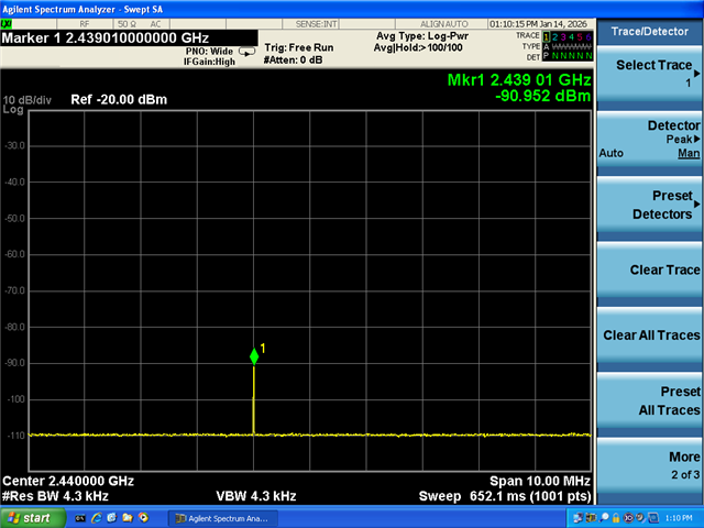
During the transmission and reception performance test, I found that the LE1M's maximum sensitivity was only -92 dBm, while the LE2M's maximum sensitivity was only -89 dBm. These values were measured using the IQ and added pathloss. The data do not match sensitivity of -96dBm in datasheet. Could you please confirm whether the configuration mode for SDK 2.6.1 is nRF mode?

Parents
  • Hello Star Tong,
    Regarding the sensitivity, it comes down to layout and implementation as well. So what sort of HW did you run the test on? Are you able to compare performance with a nRF52832 DK?
    The results we have reported in the product specification come from performance on boards using the reference schematic and layout with an ideal transmitter. It's optimum conditions, but this is what we would expect to see customers getting close to as well with a reference schematic and layout.
    ---------------------------------------
    I don't understand what you are asking here:
    "Could you please confirm whether the configuration mode for SDK 2.6.1 is nRF mode?"
    May I ask you to elaborate  what you mean by this?
    Best regards
    Asbjørn
  • Hi Asbjørn,

    Thank you for your reply.

    I tested on my own custom-designed product board.

    Regarding the layout issues you mentioned, I have the following additional comments from a hardware perspective:

    1. I verified the Tx performance aligns with the link budget, so sensitivity degradation due to mismatch can be ruled out.

    2. If the issue stemmed from desensitization, the 3dB degradation observed at LE2M compared to the datasheet would imply over 6dB degradation at LE1M—not just another 3dB. Currently, the 3dB sensitivity difference between LE1M and LE2M aligns with theoretical calculations.

    3. I noticed the following statement in the datasheet:

    'Typical sensitivity applies when ADDR0 is used for receiver address correlation. When ADDR[1...7] are used for receiver address correlation, the typical sensitivity for this mode is degraded by 3dB.'

    Therefore, I request your assistance in verifying whether any errors exist in the register configuration at the software level.

    Best Regard.

    Star.Tong

  • Hi Asbjørn,

    Our software told me that he use the standard SDK and the version is 2.6.1.

    Would you mind tell me how can I check the information related to the address?

    I use the Litepoint MW-7G as generator during test, and the waveform file is attached.

    Thanks!

    Best Regard.

    Star.Tong

  • Hello Star.Tong,

    you can check by either reading the registers or checking what you write to those registers in your FW while doing the test.

    If you are using ADDR0, it would be what is configured as BASE0 and PREFIX0.AP0, these two specific registers have these fields:
    BASE0:docs.nordicsemi.com/.../radio.html

    PREFIX0.AP0: https://docs.nordicsemi.com/bundle/ps_nrf52832/page/radio.html#d939e14642

    You would also have to know which address you are sending packages to, so that depends on what you have configured the LitePoint to transmit. I assume you have set it up to a format of this kind: https://docs.nordicsemi.com/bundle/ps_nrf52832/page/radio.html#d939e132 The "ADDRESS" there should match BASE0 and PREFIX0.AP0 to send to logic channel 0 which has the best sensitivity.

    Best regards

    Asbjørn

  • Hi Asbjørn,


    The software's response is as follows. Please help me check it:

    BASE@0x4000151C = 0x89bed600

    BASE@0x40001524 = 0x0000008e

    BASE@0x40001530 = 0x00000001

    Best Regards.

    Star

  • Hello Star,
    ''
    It seems you have address 0x89bed68e configured for ADDR0. The remaining question is what HW are you measuring on and with? Is it a custom board and what do you mean with "1. I verified the Tx performance aligns with the link budget, so sensitivity degradation due to mismatch can be ruled out." What is aligned? What output power did you configure and what specifically did you measure? 
    Best regards
    Asbjørn
  • Hi Asbjørn,

    The custom circuit board I'm using

    When Tx setting is 4, I measure 3.5dBm at the antenna end, corresponding to 4.1dBm at the chip output, with very flat in-band power.

    I've measured PWR, Frequency error, ACP, ect... all of them are fine.

    Best Regards.

    Star

Reply Children
Related