
Hi,
We've been using the PPK II for basically every IoT project we've carried out in the last few years, and it has been an incredibly useful tool.
Our standard use case is using it in source mode to replace a battery during development for IoT products and we're really happy with the results. However, during some measurements for projects that have a DC/DC converter after the battery (be it buck or buck-boost), we observed some weird behaviors and inconsistencies.
Examples of behaviors that we're seeing when measuring boards with DC/DC converters:
- High (> 0.8A) "phantom" current spikes. After investigating in the Devzone, it seems they're caused because of the switching logic inside of the PPK. We can live with them because they doesn't affect the average current too much, but it's worth mentioning that we observe them way less using PPK version 4.1.2 than the latest one (as seen in this post). Also, if we try to measure after the DC/DC (for example in the 3V3 output), these spikes are not there.
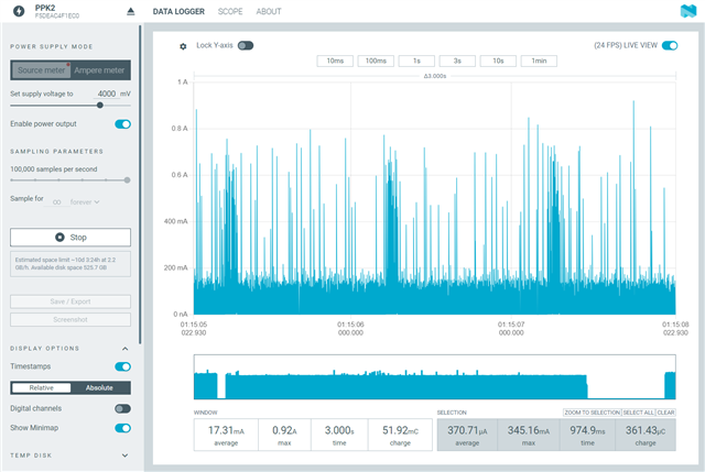
- Variable "noise floor", that significantly increases the average current sometimes. We've tried to place a capacitor right at the output of the PPK as suggested in another Devzone post, and we observe that it helps alleviating the issue as you can see in these screenshots. Left one is without capacitor, right one with it.
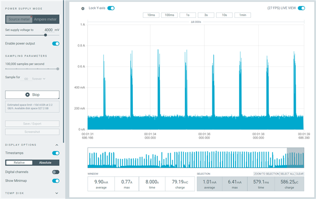
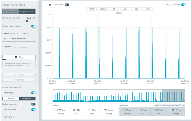
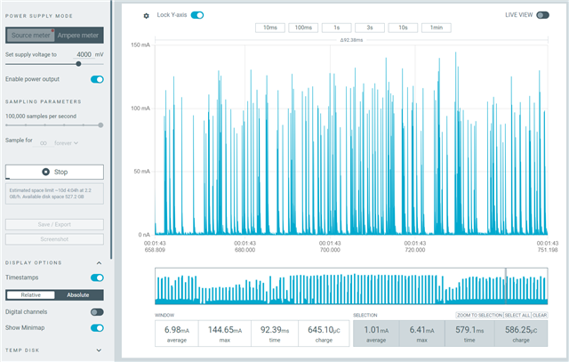
Zooming on the "floor" area betweek peaks you can observe the difference too (scale is a bit different, sorry about that)
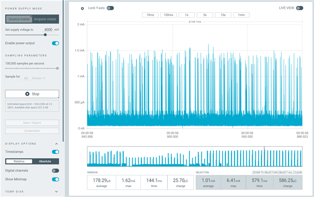
What is the reason for this behavior? Which one of the measurements should we take as the most correct one?
- Also, trying different boards with the exact same hardware and exact same firmware, we observe differences in consumption. I don't have screenshots of this, but one recent example was one board measuring 150 uA and another measuring 400 uA. We thought there was some hardware issue and thoroughly reviewed everything, until we plugged both of the boards to a Monsoon Power Monitor and in both of them we read 400 uA. On paper, Power Monitor has a way lower sampling frequency (5 kHz) so aliasing from switching regulators should be affecting even more; but with it we don't observe the previous phenomena. Again, measuring at the DC/DC output (bypassing the regulator), gives more consistent results but we can't always do this.
Are we doing something wrong, or are there some limitations of the PPK2 that we're not considering?
Best regards and thank you,
Enrique


