Output power nRF52840

I am evaluating the output power of a testboard that uses the nRF52840-QFAA. 

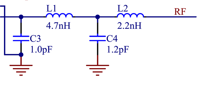
The matching network closely resembles the recommended network in the datasheet (shown in figure below). In my network, C3 = 0.8 pF, and L2 = 2.7nH due to availability of the components in our lab. 

The nRF is configured for continuous transmission on 2.4 GHz at an output power of +8 dBm.

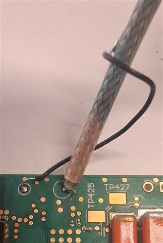
I am measuring using a spectrum analyzer with a 50ohm input directly on the RF connector. 

The measured power is only -5 dBm, which is 13 dB lower than expected.

I understand that the cables could add some losses and that the power spec is +/-4dB, But together it shouldn't add up to 13 dB.


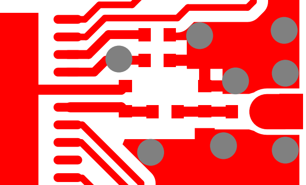
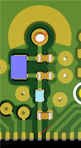
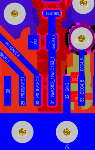
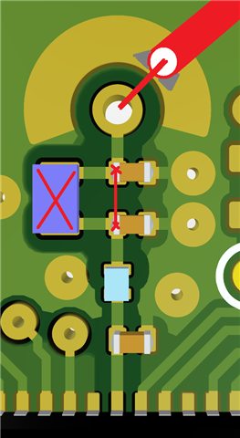
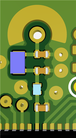
I'm also including a screenshot of the PCB. For this test, the capacitor at the output is not populated and a pigtail is soldered directly to the RF output pin to interface with the spectrum analyzer.

I would appreciate any help to identify or verify this measurement result.

  • Hi Francesc,

    The layout in the picture has several issues. The first shunt capacitor must only connect through PAVSS to the exposed pad, and must not be connected to the top GND pour. I cannot see how PAVSS is connected on your picture, could you post a screenshot in the 2D design view?

    There is also an inductor which is way too big, it should be 0201 size and placed inline with the rest of the components. Larger components have more parasitics, and could behave totally differently on high frequencies, even with the same value.

    Small deviation from the reference value could cause problems with harmonic emissions, but for the output power, there shouldn't be much difference.

    Please see the reference layout. This is how you should implement it:

    Just to be clear, at which point are you measuring the output power, in the picture below? Can you include a photo of the soldered pigtail?

    Also, what firmware are you using for the test?

  • Hi Szabolcs, 

    Thank you for your reply!

    The shortest path from the first shunt capacitor to the PAVSS pin is through the ground plane on the bottom layer and coming up to the exposed pad. See the included figure.


    I am measuring at point two in your annotated screenshot. (The picture is from the backside of the pcb)


    The FW during testing is custom (developed in-house). It configures the nRF in continuous transmission mode at 2.4 GHz with the power level configured at +8 dBm.

  • Ok, thank you for clearing things up.

    If you haven't already, you should test your firmware on a Nordic DevBoard, and see if you get the expected power output, just to make sure.

    The pigtail connection is not very good, the ground connection is not sufficient on these frequencies. You should solder the outer shield at the end of the coaxial cable to the ground very close to the connection point, trying to minimize the length of the discontinuity. Remove the large inductor (you could even remove the pads under it), and short the pads between the capacitors. (Ideally, you could also solder a 2.2nH 0201 inductor between the caps, if you have it, but it's not critical for this test, a short will do.) You can see what I mean in this sketch below:

    Do you know the part number of the 4.7nH inductor?

  • Hi Szabolcs, 

    Thank you for the suggestions, we will test the firmware on a devkit and improve the pigtail connection.

    In the meantime, here is the fw file that we use. It uses the nrf_radio HAL driver from nRF5 SDK v.17.1.0.
    Perhaps you can already flag some issues there?

    // nRF5 SDK includes
    #include <nrf_radio.h>
    #include <nrf_delay.h>
    #include <nrf_drv_clock.h>
    #include <app_scheduler.h>
    #include <sdk_macros.h>
    
    // Local includes
    #include "rf.h"
    #include "ble/bf_ble.h"
    #include "status.h"
    #include "debug/log.h"
    
    static uint16_t CwFreq;
    static uint8_t CwTxPower;
    static bool IsRunning = false;
    
    /****************************************************************************/
    /* INTERNAL FUNCTIONS DEFINITIONS                                           */
    /****************************************************************************/
    //----------------------------------------------------------------------------
    static bool IsTxPowerValid(int8_t txPower)
    {
        switch ((uint8_t)txPower)
        {
            case NRF_RADIO_TXPOWER_POS8DBM:
            case NRF_RADIO_TXPOWER_POS7DBM:
            case NRF_RADIO_TXPOWER_POS6DBM:
            case NRF_RADIO_TXPOWER_POS5DBM:
            case NRF_RADIO_TXPOWER_POS4DBM:
            case NRF_RADIO_TXPOWER_POS3DBM:
            case NRF_RADIO_TXPOWER_POS2DBM:
            case NRF_RADIO_TXPOWER_0DBM:
            case NRF_RADIO_TXPOWER_NEG4DBM:
            case NRF_RADIO_TXPOWER_NEG8DBM:
            case NRF_RADIO_TXPOWER_NEG12DBM:
            case NRF_RADIO_TXPOWER_NEG16DBM:
            case NRF_RADIO_TXPOWER_NEG20DBM:
            case NRF_RADIO_TXPOWER_NEG30DBM:
            case NRF_RADIO_TXPOWER_NEG40DBM:
                return true;
            default:
                return false;
        }
    }
    
    //----------------------------------------------------------------------------
    void StartCwSched(void *evtData, uint16_t evtSize)
    {
        // SoftDevice must be disabled to control RADIO peripheral
        if (Ble_IsEnabled())
        {
            ret_code_t ret = Ble_Disable();
            if (ret != STATUS_SUCCESS)
            {
                LOG_ERROR("Error when disabling BLE stack: %d", ret);
                return;
            }
        }
    
        // Request HF crystal oscillator for proper RADIO behaviour
        if (!IsRunning)
        {
            nrf_drv_clock_hfclk_request(NULL);
            while (!nrf_drv_clock_hfclk_is_running())
            {
                // Wait until HF clock is started
            }
        }
    
        // Power-cycle the RADIO to re-initialize it
        nrf_radio_task_trigger(NRF_RADIO_TASK_DISABLE);
        nrf_radio_power_set(false);
        nrf_delay_ms(10);
        nrf_radio_power_set(true);
    
        // Configure and start the RADIO
        nrf_radio_mode_set(NRF_RADIO_MODE_BLE_1MBIT);
        nrf_radio_frequency_set(CwFreq);
        nrf_radio_txpower_set(CwTxPower);
        nrf_radio_task_trigger(NRF_RADIO_TASK_TXEN);
    
        IsRunning = true;
    }
    
    /****************************************************************************/
    /* EXTERNAL FUNCTIONS DEFINITIONS                                           */
    /****************************************************************************/
    //----------------------------------------------------------------------------
    ret_code_t Rf_StartCw(uint16_t freq, int8_t txPower)
    {
        // Check frequency is valid
        if ((freq < 2360) || (freq > 2500))
        {
            return NRF_ERROR_INVALID_PARAM;
        }
    
        // Check TX power is valid
        if (!IsTxPowerValid(txPower))
        {
            return NRF_ERROR_INVALID_PARAM;
        }
    
        LOG_INFO("Starting RF continuous wave - freq: %dMHz - tx_power: %ddBm", freq, txPower);
    
        CwFreq = freq;
        CwTxPower = txPower;
        // Go through scheduler to avoid issue when disabling BLE stack from a BLE event observer
        return app_sched_event_put(NULL, 0, &StartCwSched);
    }
    
    //----------------------------------------------------------------------------
    ret_code_t Rf_Stop(void)
    {
        if (IsRunning)
        {
            nrf_drv_clock_hfclk_release();
            nrf_radio_task_trigger(NRF_RADIO_TASK_DISABLE);
            IsRunning = false;
    
            // Enable BLE stack
            return Ble_Enable();
        }
    
        return NRF_SUCCESS;
    }

  • Hi Francesc,

    Your code looks good to me, but I'm not an expert on firmware, so one of my coworkers will also check it. In the meantime, could you please also test your device with the Radio Test sample project?

Related