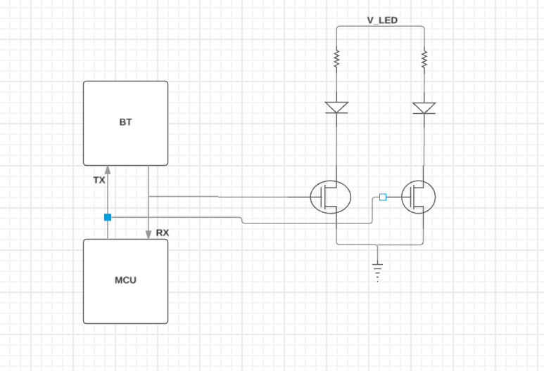
I want to know which pins serve the purpose of TX and RX in nRF51822. I suspect its the ANT1 and ANT2 but i want to confirm and also if the following would be a good way to place status LEDs on the TX and RX lines
www.nordicsemi.com/.../nRF51822
Pin functions are described on p12 of the Product Specification (v3.1):
ANT1 RF Differential antenna connection (TX and RX).
ANT2 RF Differential antenna connection (TX and RX).
Note that these are the RF connections - you would not connect these to an MCU!
Presumably, your diagram is intended to indicate a UART connection to the MCU ... ?
As quoted above, these are the antenna connection points.
Have you looked at the product specification?
Or the reference designs: www.nordicsemi.com/.../nRF51822
Or the schematics of the Dev Kits, Dongles, etc: www.nordicsemi.com/.../nRF51822
As quoted above, these are the antenna connection points.
Have you looked at the product specification?
Or the reference designs: www.nordicsemi.com/.../nRF51822
Or the schematics of the Dev Kits, Dongles, etc: www.nordicsemi.com/.../nRF51822