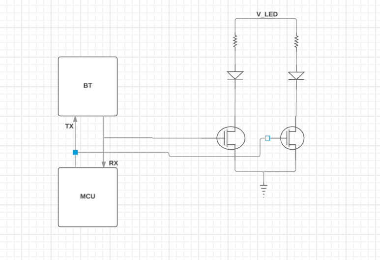
I want to know which pins serve the purpose of TX and RX in nRF51822. I suspect its the ANT1 and ANT2 but i want to confirm and also if the following would be a good way to place status LEDs on the TX and RX lines

I want to know which pins serve the purpose of TX and RX in nRF51822. I suspect its the ANT1 and ANT2 but i want to confirm and also if the following would be a good way to place status LEDs on the TX and RX lines

www.nordicsemi.com/.../nRF51822
Pin functions are described on p12 of the Product Specification (v3.1):
ANT1 RF Differential antenna connection (TX and RX).
ANT2 RF Differential antenna connection (TX and RX).
Note that these are the RF connections - you would not connect these to an MCU!
Presumably, your diagram is intended to indicate a UART connection to the MCU ... ?
can you tell me what will happen to the TX and RX for this case? And what is the need of ANT1 and ANT2? I saw the product specification but couldn't understand
can you tell me what will happen to the TX and RX for this case? And what is the need of ANT1 and ANT2? I saw the product specification but couldn't understand