Hi guys
I am trying to program a nrf51822 module but it is not recognized by the development kit.
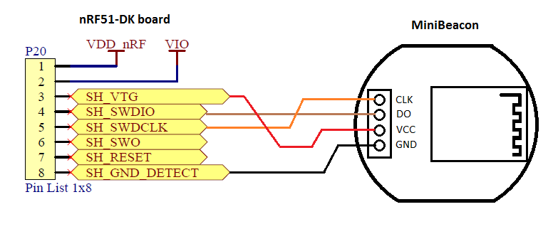
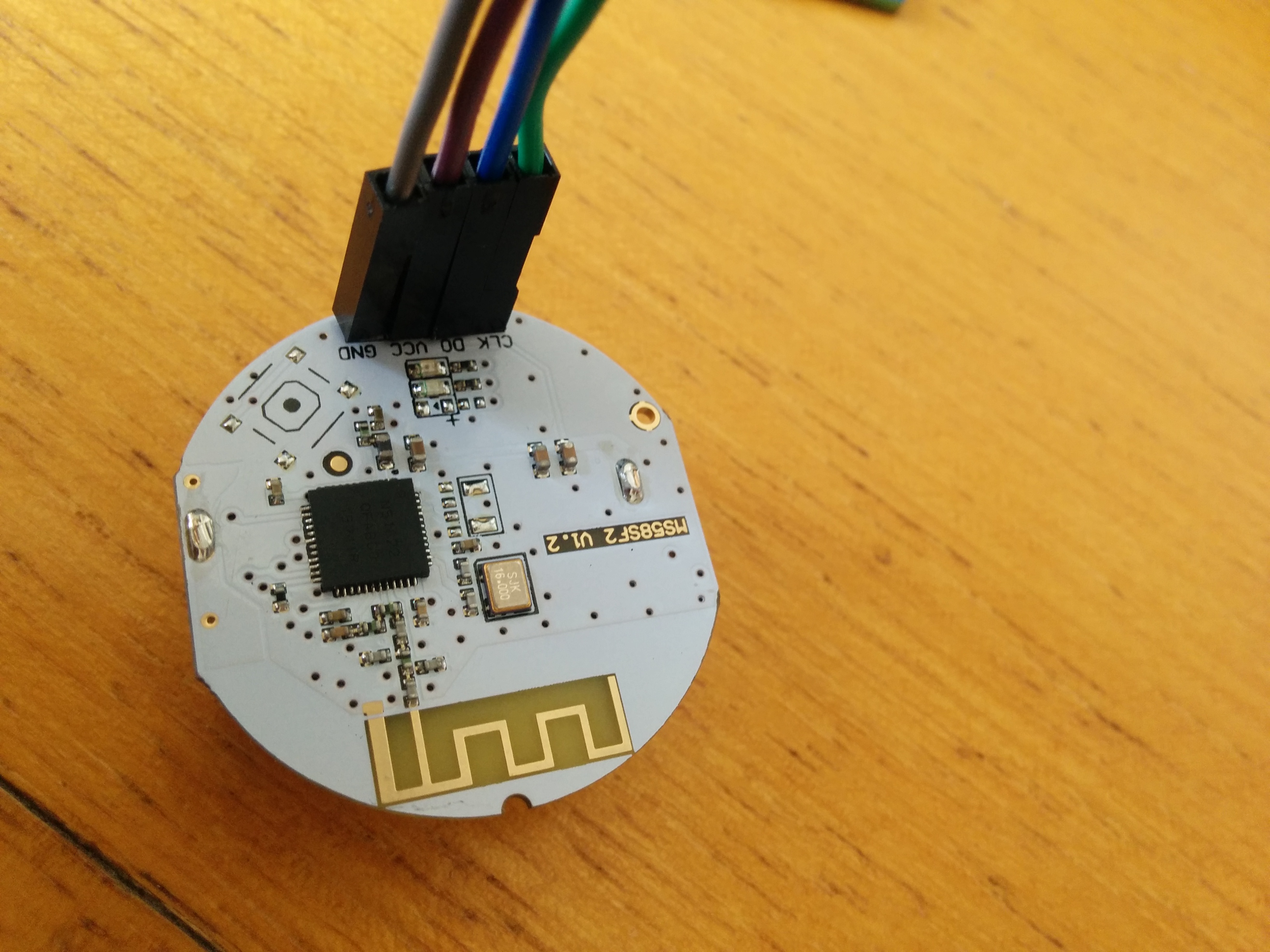
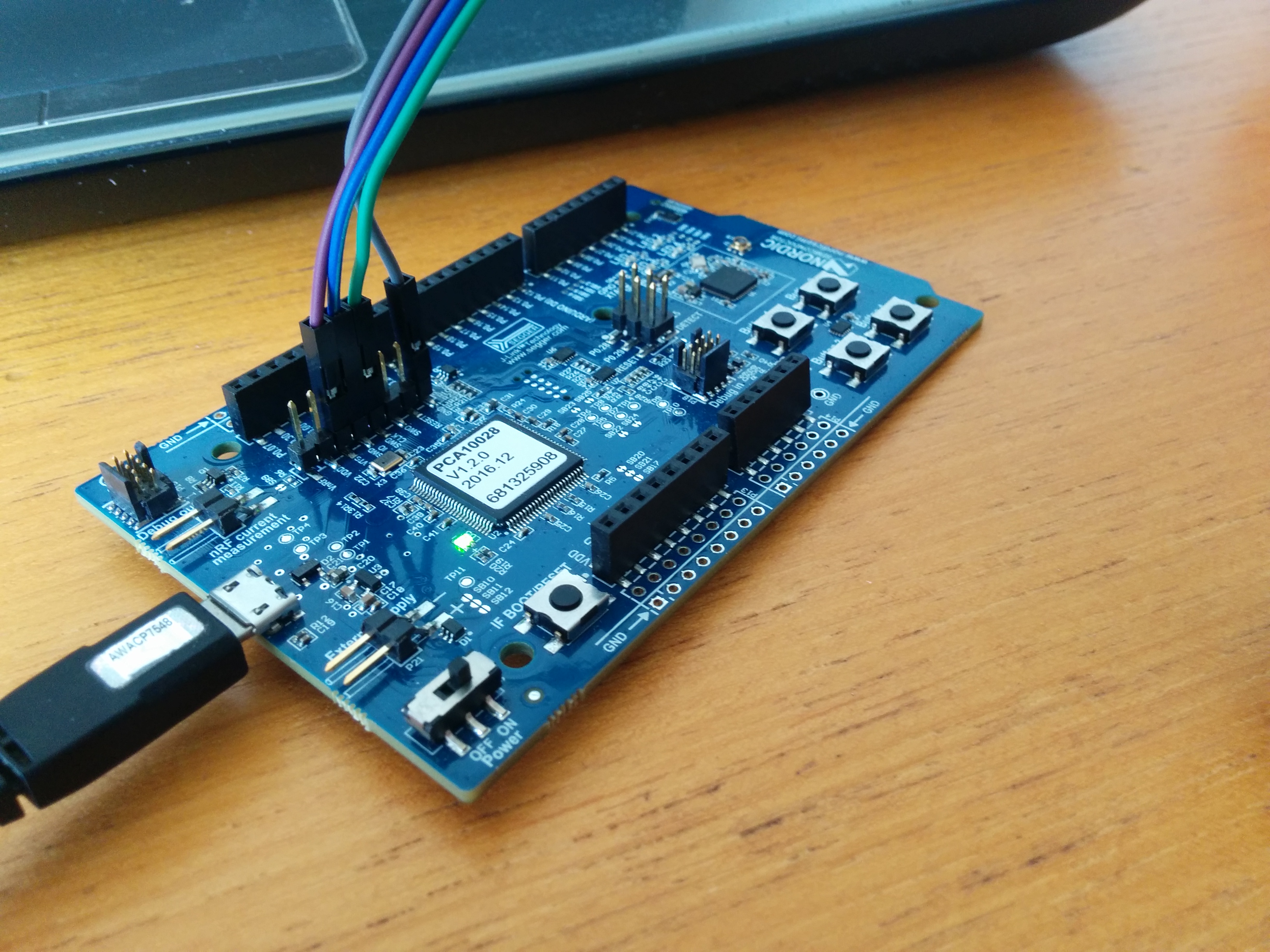
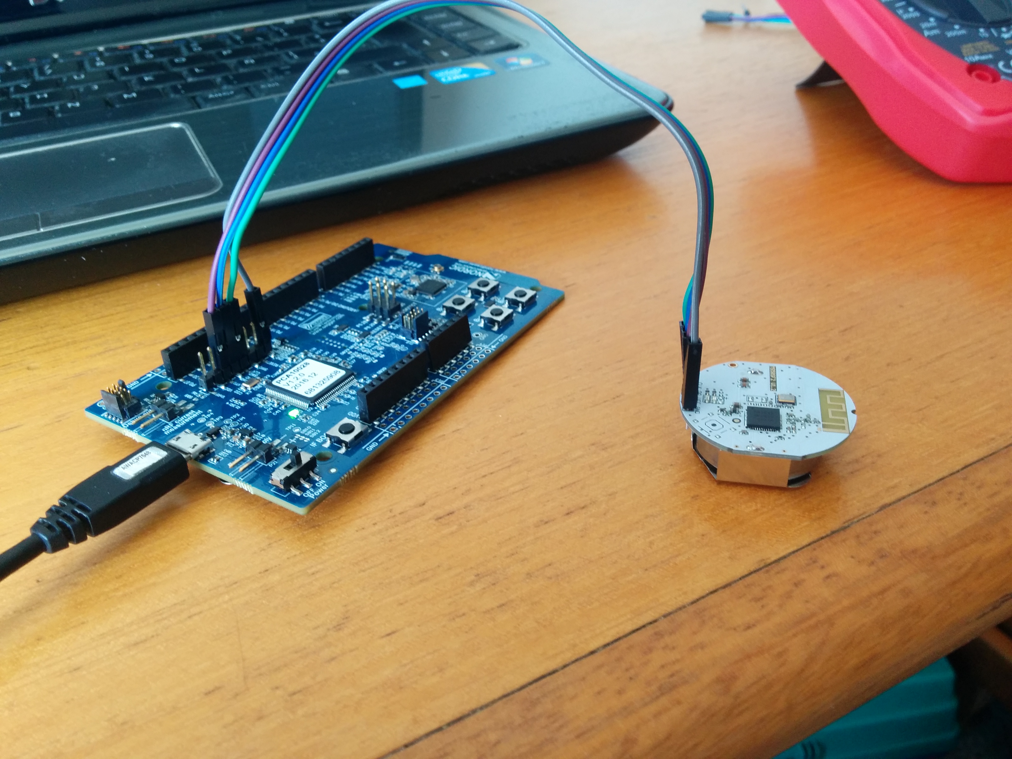
These are the pins that I am using:


I can not see the module with NRFGo on Windows or on linux with Jlink console.
Any idea?
Thanks in advance!
Hi guys
I am trying to program a nrf51822 module but it is not recognized by the development kit.
These are the pins that I am using:


I can not see the module with NRFGo on Windows or on linux with Jlink console.
Any idea?
Thanks in advance!
My voltmeter says I'm outputting 2.86volts to my custom PCB through the nRF 52 DK and the DK picks it up fine.
Hi,
previous answers are correct that you need to short VCC to VTG.
Additionally you need a proper GND connection to your circuit, as GND_DETECT (pin 8 on P20) is an "input" that triggers use of external module (might be an oversimplification). I suggest you short one GND from connector P1 to your module, and short another GND to GND_DETECT.
Best regards,
Borut
Hi endnode
Thanks for answering. I have tried with the connection of P20 pins 2 and 3 without results.
I am not using P20 pin 1. How do you use it?
Thanks in advance
Hi, hard to say what's wrong then. For me it works even when I play with second nRF5x DK board (if I bridge P20 SWD PINs to standard 10-pin SEGGER connector then I can flash nRF5x chip on the other DK without problems) so it might indicate problems with this one particular custom board. I'm using Pin 1 of P20 (VDD_nRF) to power target board by 3V. Yes, you can use other pins from other headers on nRF5x DK to achieve the same...
Cheers Jan
Hi Martin
Thanks for answering. I have tried with the connection of P20 pins 2 and 3 without results.
Without the pins 2 and 3 short I have these voltages:
This is the Segger Jlink output on Ubuntu:
nicolas@nicolas:~$ sudo JLinkExe -device nRF51822 -speed auto -if swd
SEGGER J-Link Commander V5.12e (Compiled Apr 29 2016 15:06:32)
DLL version V5.12e, compiled Apr 29 2016 15:06:27

Connecting to J-Link via USB...O.K.
Firmware: J-Link OB-SAM3U128-V2-NordicSemi compiled Mar 15 2016 18:03:17
Hardware version: V1.00
S/N: 681325908
VTref = 3.300V


Type "connect" to establish a target connection, '?' for help
J-Link> connect
Device "NRF51822_XXAA" selected.
TotalIRLen = ?, IRPrint = 0x..000000000000000000000000


Found SWD-DP with ID 0x0BB11477
Found Cortex-M0 r0p0, Little endian.
FPUnit: 4 code (BP) slots and 0 literal slots
CoreSight components:
ROMTbl 0 @ F0000000
ROMTbl 0 [0]: F00FF000, CID: B105100D, PID: 000BB471 ROM Table
ROMTbl 1 @ E00FF000
ROMTbl 1 [0]: FFF0F000, CID: B105E00D, PID: 000BB008 SCS
ROMTbl 1 [1]: FFF02000, CID: B105E00D, PID: 000BB00A DWT
ROMTbl 1 [2]: FFF03000, CID: B105E00D, PID: 000BB00B FPB
ROMTbl 0 [1]: 00002000, CID: B105900D, PID: 000BB9A3 ???
Cortex-M0 identified.
This device corresponds to nrf51DK's chip. I can't see module's chip.
Thanks in advance!