
Hi guys
I am trying to program a nrf51822 module but it is not recognized by the development kit.
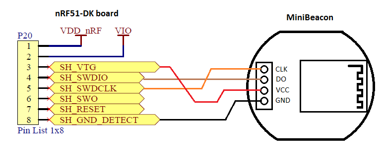
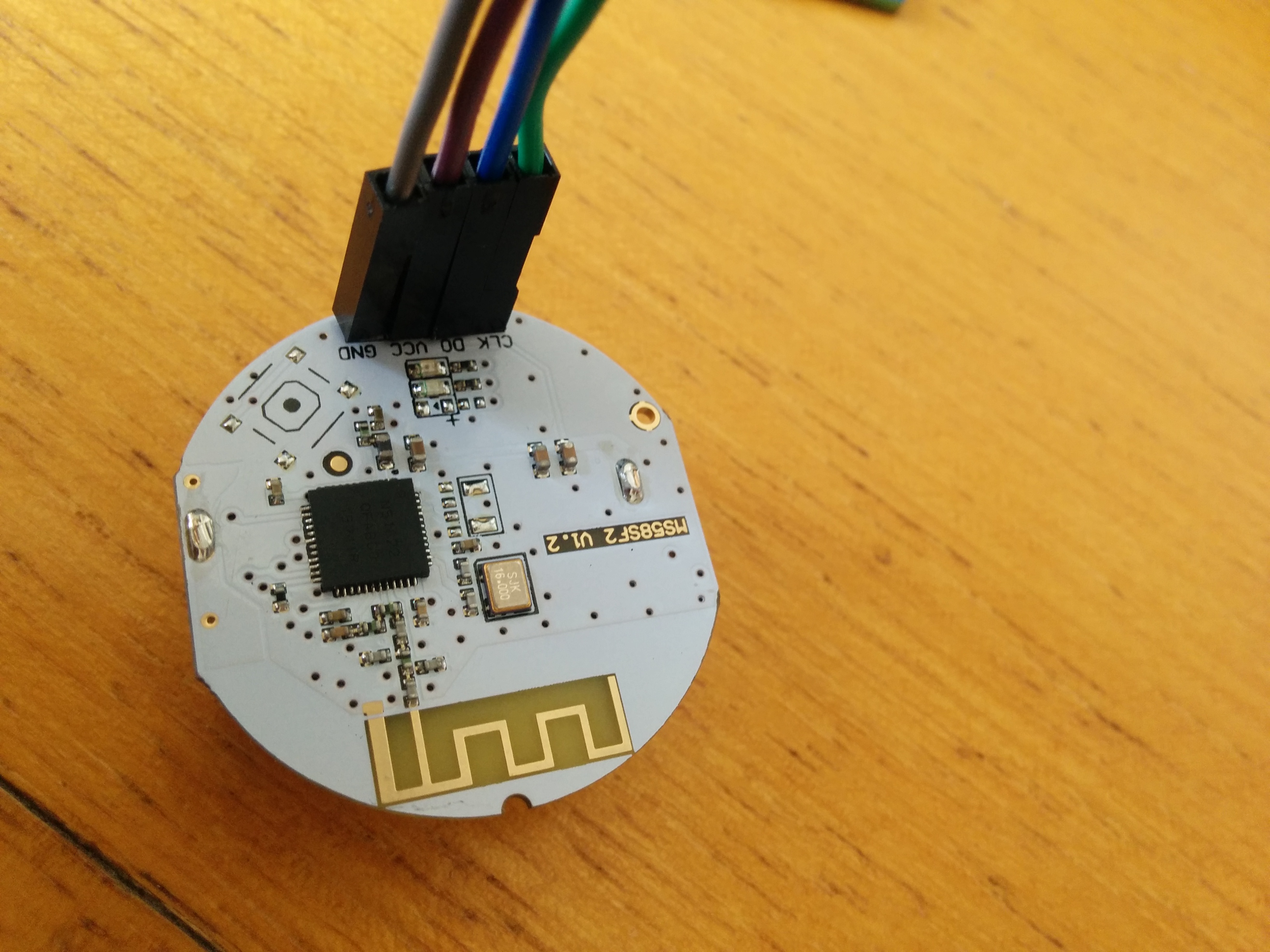
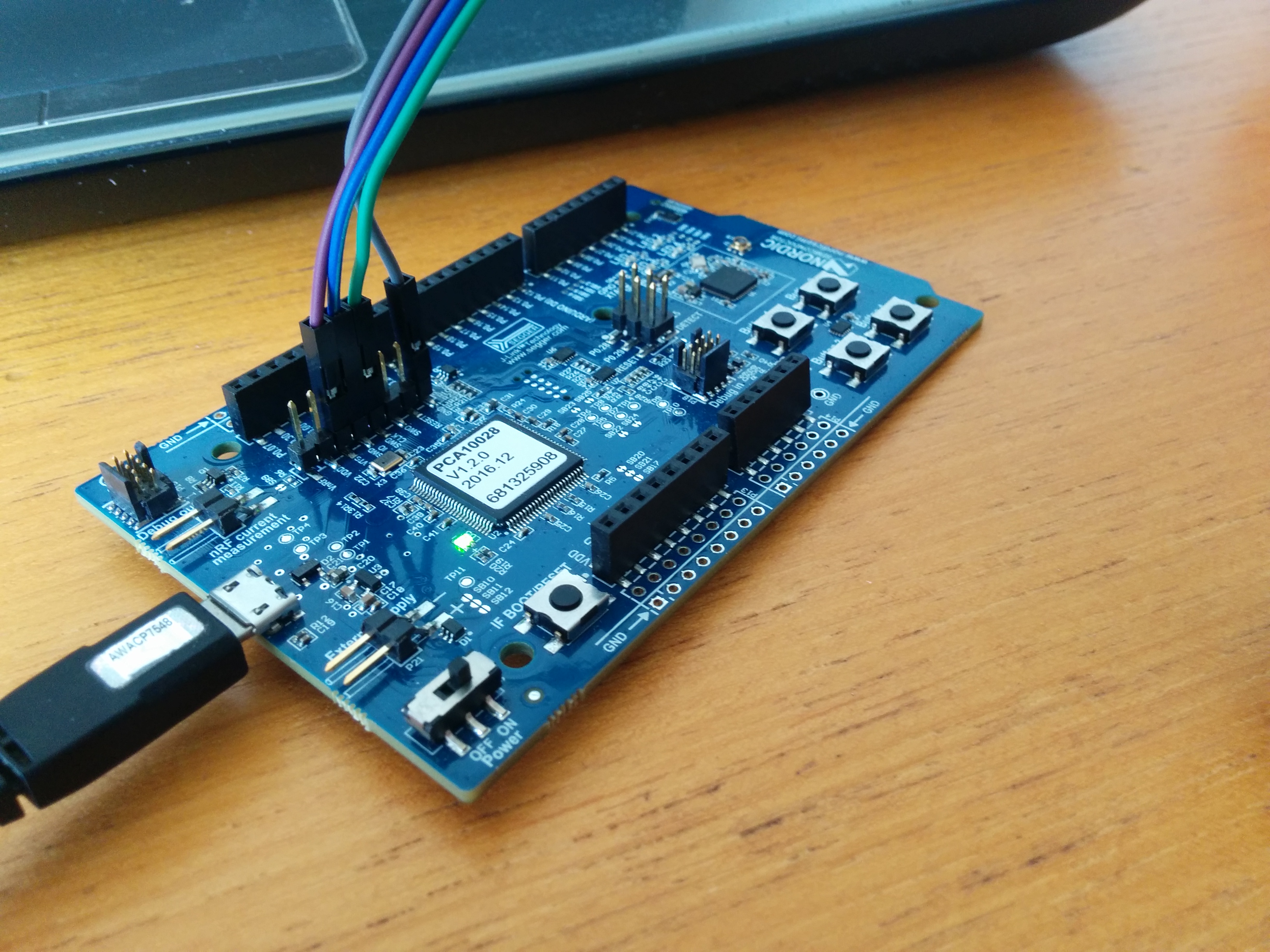
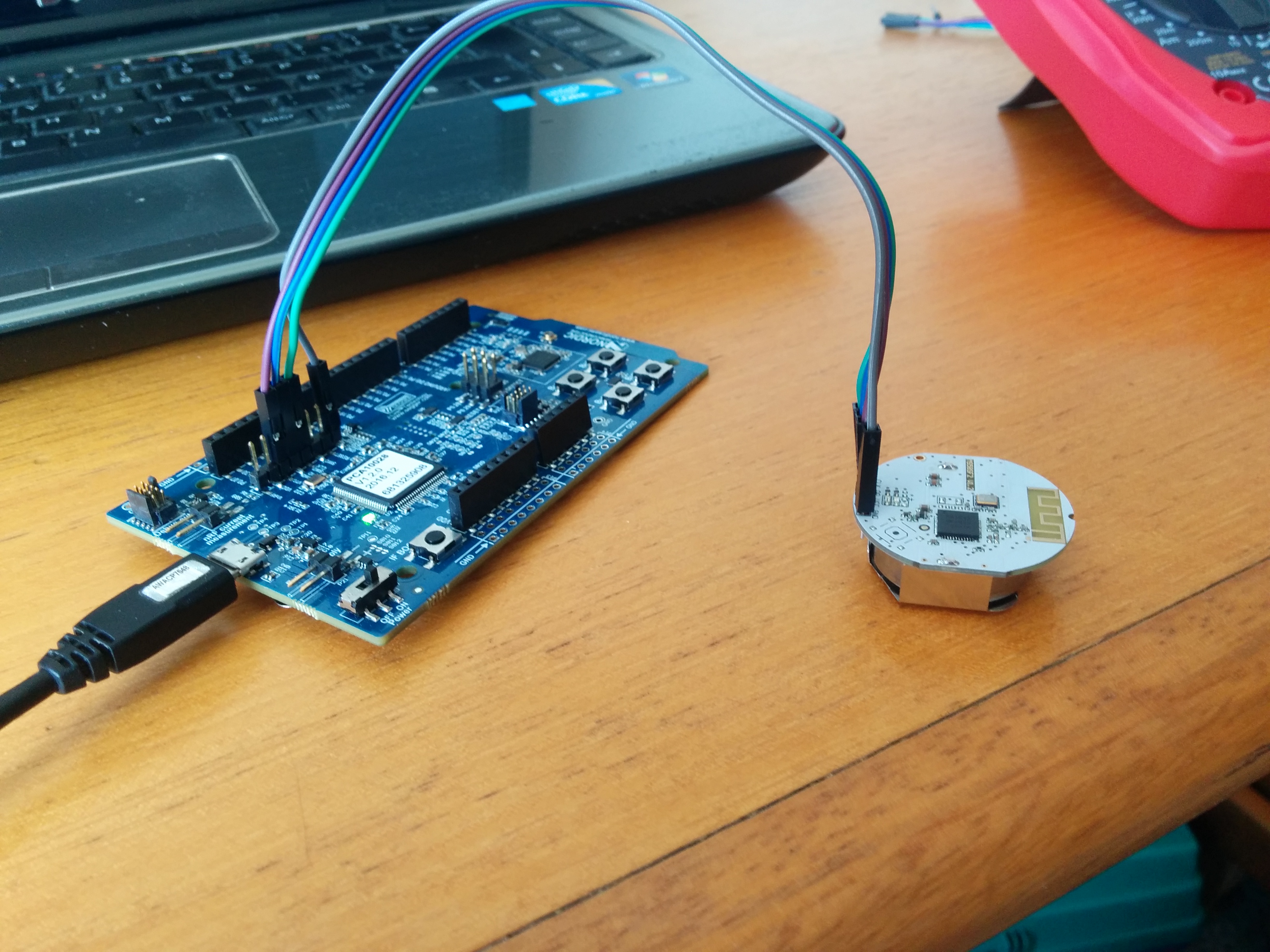
These are the pins that I am using:
I can not see the module with NRFGo on Windows or on linux with Jlink console.
Any idea?
Thanks in advance!
Hi guys
I am trying to program a nrf51822 module but it is not recognized by the development kit.
These are the pins that I am using:
I can not see the module with NRFGo on Windows or on linux with Jlink console.
Any idea?
Thanks in advance!


