
 HI,
Can anybody give me the connections to a BMD-300 with nRF52DK and the steps to program a BMD-300 from scratch? Which document provides the information, if there is any?
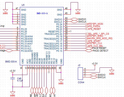
HI,
Can anybody give me the connections to a BMD-300 with nRF52DK and the steps to program a BMD-300 from scratch? Which document provides the information, if there is any?
thanks, Vishnu
HI,
Can anybody give me the connections to a BMD-300 with nRF52DK and the steps to program a BMD-300 from scratch? Which document provides the information, if there is any?
thanks, Vishnu

