This post is older than 2 years and might not be relevant anymore
More Info: Consider searching for newer posts

nRF240L01 with STM8L051F3

Hi, I am looking for procedure to make it work nRF240L01? I am getting documents for Arduino but as you know that is not understandable, with Arduino it worked but i don't understood. Now i want to make it work with STM8L051F3. STM8L051F3 is 8 bit ultra low power controller. I am looking for procedure like what steps i have to follow so i can send data to another nRF240L01. Which commands i have to send. I want to transmit data after every 1 sec and then it will go in power down. Receiver will be always in receiver mode.

Parents
  • Thank yo very much for your reply

    I will do exactly as the example you sent an inform results in about 2 days

    I have well tested the SPI comunications , working OK

    ---------------------------------------------------------------

    Level compatibility with 5VuP VCC.

     I have measured  CE  CSN  MOSI  and they are OK about input levels for uP   Vcc = 5V)

    MISO output with 4K7  resistor to +5V  also has complete 0 an 5V range.

    For  IRQ  similar resistor to +5V has no effect. I didn't find this information in data sheet

    If uP has some problem with 3.3V as high level, I can reduce the Vcc supply to about 4V or add a small mosfet transistor as inverter (modifying as needed IRQ polarity definition)

    Regards, Osvaldo

  • Hi Osvaldo

    Sorry for the slow response, I was out in Easter vacation until today. 

    Are you still having issues with this? 

    The nRF24L01+ will only work in the 1.9-3.6V range, and it is important that you keep the supply and the interface signals within this range. 

    If you are unable to use an MCU that supports this level you will need some kind of level shifters on the signals, and a separate regulator for the nRF device to provide the supply voltage. 

    Best regards
    Torbjørn

  • Tusen takk for all comments so far.  I have made changes suggested, but still no receive between two separatre units.  However I am getting a packet received indication in my code when I transmit from each unit in its own receiver. Is it expected that if PTX and PRX have same address a unit will lreceive its own packets?   This would indocate progress to me!

  • Hi,


    Are you certain that you are using this command?

    That should be cmd=0xB0.


    VE3ID said:
    I have made changes suggested, but still no receive between two separatre units.  However I am getting a packet received indication in my code when I transmit from each unit in its own receiver. Is it expected that if PTX and PRX have same address a unit will lreceive its own packets?   This would indocate progress to me!

    Which event do you receive specifically here? If "NOACK" is used, a STATUS::TX_DS shall be set.


    Kind regards,

    Håkon

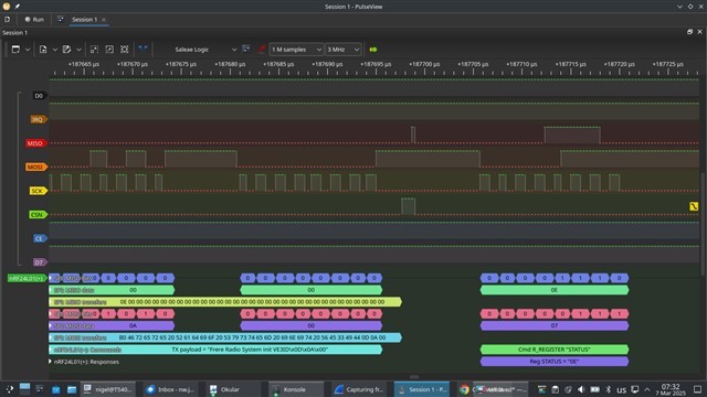
  • Thanks to all for the help I have had so far.  I am now able to send and receive complete packets, however, there is a terrible intermittency in my reading the status register to see if a packet has been sent out, sometimes it hangs on the <send 0x07> <listen for status including TX_DS> loop for many seconds!  I will try and include graphic of logic anal yser.

  • Hi,


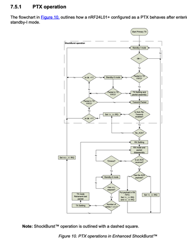
    TX_DS should occur quickly, especially when using "W_TX_PAYLOAD_NO
    ACK", as shown in the PS chapter 7.5.1:


    If you have a stored logic trace of the SPI communication, I would be happy to have a look.


    Kind regards,

    Håkon

  • Thank you. The graphic would be pretty big, but my analyser is Pulseview and its output can go to srzip session file format data files, can you read those?

Reply Children
  • I tried to upload the srzip output in case you can read it, but it would not let me :-(  Thanks, Nigel

  • Hi Nigel,


    PulseView is not a problem.

    VE3ID said:
    I tried to upload the srzip output in case you can read it, but it would not let me

    Unfortunately, the web engine is a bit restrictive in terms of file extensions. If you archive the file (tar, gz, bz, zip, rar, etc), you should be able to select and upload your file.


    Kind regards,

    Håkon

  • Hi,


    Thank you for the traces.

    It seems that the device reports back "0x0F" on MISO to each command (0xFF / 0x07), and this does not change throughout the trace itself.

    The CE pin is set high before the payload is uploaded, which is fine, but has its drawbacks, as CSN is also never set high (ie. idle) between each poll. Try setting the CSN pin idle between each poll.

    This is required when CE=1, as shown in the ps chapter 6.1.6:

    If CE is held high all TX FIFOs are emptied and all necessary ACK and possible retransmits are carried out. The transmission continues as long as the TX FIFO is refilled. If the TX FIFO is empty when
    the CE is still high, nRF24L01+ enters standby-II mode. In this mode the transmission of a packet is
    started as soon as the CSN is set high after an upload (UL) of a packet to TX FIFO.


    What is a bit strange here is that you upload one payload, but the STATUS register returns 0x0F for the remainder of the period, indicating that the TX_FIFO is filled up. Was there any payloads uploaded prior to this trace?


    Kind regards,

    Håkon

  • Tusen takk, Håkon,

    That has fixed that problem.  Now I just have to undo all the changes I made in troubleshooting and trying to fix that myself!  To be honest, I have great difficulty reading the state diagram (my eyes are 71 years old :-) with very faint graphics on white background.  Perhaps you have another hi-res copy that is not embedded in another document to send me to avoid me leaning on you for your kind advice :-)

Related