Hi ,I am using nrf52 DK with mpu9255.I am using source code given here here.of this link,I have taken 'nrf5-ble-data-ready-interrupts' example .code builts fine in keil v5 though.I am not getting accel values.
help will be appreciated.
Hi ,I am using nrf52 DK with mpu9255.I am using source code given here here.of this link,I have taken 'nrf5-ble-data-ready-interrupts' example .code builts fine in keil v5 though.I am not getting accel values.
help will be appreciated.
Hi,
I have pushed an updated 'nrf5-ble-data-ready-interrupts' example to github that I have tested with a PCA10056 and an MPU9255.
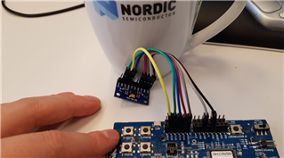
Note that to use pin 17, 19, 20, and 21 on the PCA10056 you will need to cut some solder bridges and do some soldering as these pins are not actually connected to the P24 header on the kit by default (as is described in the image you have posted): Solder bridge configuration.
Hi MartinBL,
I amnot using PCA 10056.I am using PCA10040.can you share link of updated git hub example
thank you
Hi
Yes,as mentioned earlier ,I have programmEd nrf52 dk with soft device s132 then loaded dk with example code.
Can you share your 52dk interfacing with mpu9255 diagram/image ?
Here you go:
Did you try my test hex file?
Note that I have bypassed the voltage regulator on my MPU9255 breakout board with a solder bridge. Hence I can feed it with VDD from my nRF52DK, and not 5V as it seems like you do.
Yes ...Its working now with both SPI/TWI.
i am using same code for board .I have changed SCL and SDA as follows
In main.c
#define MPU_MPU_INT_PIN 12 //as INT pin10 for given kit .Physical number 12
in nrf_drv_mpu_twi.c
#define MPU_TWI_SCL_PIN 9
#define MPU_TWI_SDA_PIN 8
because Pin p0.06 i.e physical number 8 and P0.07 i.e physical pin number 9
I am not getting values for accel and magneto .please suggest which about pin number/code change
Here i am using nRF52 DK as a debugger/programmer.another h/w is my application h/w
If you want SDA on P0.06 and SCL on P0.07 you should set:
#define MPU_TWI_SCL_PIN 7
#define MPU_TWI_SDA_PIN 6
If you want SDA on P0.06 and SCL on P0.07 you should set:
#define MPU_TWI_SCL_PIN 7
#define MPU_TWI_SDA_PIN 6
Yes .I have set and i have changed INT pin as well ,Because pin 0.08 is is connected to INT pin of mpu9250
#define MPU_MPU_INT_PIN 8
in pca10040.h file these 3 pins are used for
#define RX_PIN_NUMBER 8
#define TX_PIN_NUMBER 6
#define CTS_PIN_NUMBER 7
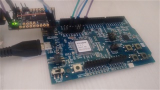
If you look on the back side of your kit you can see which pins are already being used for things like UART. In the MPU examples the UART are configured before the MPU in the code. If you "override" the UART configuration and use the UART pins for the MPU then naturally you will not see anything printed to your terminal. This is why I chose to use pin 3,4,28,29 and 30 by default in the examples since they are not being used by anything else.
yes.
1.In the code sample rate set is 5Hz, If i require to change it to suppose 25Hz ,Do i need to make here 39 instead of 199 ?
p_mpu_config.smplrt_div = 199; // Change sampelrate. Sample Rate = Gyroscope Output Rate / (1 + SMPLRT_DIV). 199 gives a sample rate of 5Hz
2.Data is sent directly when i enable the notification after connection to device .what changes do i need make if i want to send data only after i write a value to characteristic ?
Do i need to make here 39 instead of 199 ?
Yes.
what changes do i need make if i want to send data only after i write a value to characteristic
I advice you to study the BLE Blinky Application example. It shows how you can turn on an LED by writing to a characteristic. With a little modification you can use this to achieve what you want.
hi
i need to add manufacturer data to same example ,sdk14
can you please suggest example to refer for s132?