This post is older than 2 years and might not be relevant anymore
More Info: Consider searching for newer posts

nRF52832 IO problem

Hello!

We have nRF52832 chip on our product and we have some problem with one of its IOs.. We configured P0.16 as RX of UART, And when we run it we see this behavior of this IO:
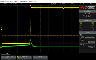
VCC (yellow) vs P0.16 (green) that configured as UART_RX

Here we see that with rising of VCC (yellow signal) IO (green) rising to almost 1V when it supposed to still at 0V. Important note: we disable and enable VCC fast here so we see that before rising of VCC it don't have 0V. This behaviour is very problematic to our system. Because we have power supply sensitive sensor that connected to this UART. This spike of voltage damage sensor that connected to this IO.

We tried to load to evaluation board same version of SW on nRF52832 and we got next result:
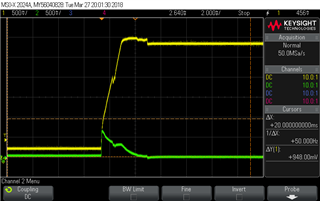
We see that also here we have the problematic spike.

When we erased the evaluation board - we got the same result.

Is this IO known as problematic?

Thank you

Parents
  • Hello, sir 

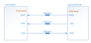
    Have you fixed your issue?  We have have similar issue, the TXD(P0.31) of nRF52832 looks like being damaged when connect to other module which operating at 3V level.

    We make a 200pcs production with  SMT, and found  there are 15+PCS have the same issue(TXD damaged) after board function test. and we don't know others will fail or not in later work time.

    thanks,

    Jason Hu

  • Hey

    Yes, we solved it. We found that the problem was the second side of the communication - this processor was damaged. We sent our TI processors to manufacturers and they confirmed that they damaged and no Nordic microprocessors 

    Maybe it is also your issue. Test it.

  • Hello, 

    Thanks for your information,  Do you mean that MSP430 is damaged and nRF52832 is well in your board?

    If it is , could you share us the  reason?  Now, with our board, it looks like the nRF52832 is damaged, and the module is ok.

    Thanks again!

    Jason Hu

  • The problem was that at power-up at some point the voltage at MSP flash was relatively low and it damaged the flash so it stopped working. This damage may be resolved only by FW update of MSP but no always.

    At some point during our problem debug we thought that nRF have problem, and we also saw no good behaviour of nordic IO and thought that ot damaged. It is the reason I opened this tread here. But at the end the problem was with MSP and after MSP replacement the design worked again.

    I would to recommend you to deassemble your nordic chip and check it at other board to ensure that it is it that damaged..

Reply
  • The problem was that at power-up at some point the voltage at MSP flash was relatively low and it damaged the flash so it stopped working. This damage may be resolved only by FW update of MSP but no always.

    At some point during our problem debug we thought that nRF have problem, and we also saw no good behaviour of nordic IO and thought that ot damaged. It is the reason I opened this tread here. But at the end the problem was with MSP and after MSP replacement the design worked again.

    I would to recommend you to deassemble your nordic chip and check it at other board to ensure that it is it that damaged..

Children
No Data
Related