This post is older than 2 years and might not be relevant anymore
More Info: Consider searching for newer posts

nRF52832 Custom Board Development Issues

Hi All!

I have been working on bringing-up a custom manufactured nRF52832 board. I have with me 6 boards, the first 3 are working fine, the other 3 are not. In both cases, the components and the procedure used is the same. I've first worked with the nRF52 Development Kit and it worked fine. The boards are designed according to the reference schematics provided by Nordic. Please find attached the schematic of my design for the board.

Node-nRF52832.pdf

Some more info on what I'm using to flash the code:

Platform -> Linux, Compiler -> armgcc, soft-device -> s132

I'm able to flash the "blinky" example code in my custom boards successfully. The path is "nRF5_SDK_15.0.0_a53641a/examples/peripheral/blinky" by connecting its SWD pins to the nRF52 Development Kit's SWD pins as seen in the picture below. The outputs were observed on 3 of the 6 boards while the other 3 failed to respond. ( Please note that all 6 boards flashed successfully)
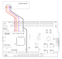
My questions are:

1. Why 3 of the 6 boards would work, and the other 3 would not?

2. To troubleshoot this, I started desoldering the crystals, first the 32.768 kHz and then the 32 MHz. And still flash happened successfully when no external crystals were connected. Is this behavior normal?

3. Can you suggest particular areas to concentrate on, so I can troubleshoot in an easier way and in lesser time?

Thanks in advance.

Best Regards,

Karan

  • 1. The schematic looks correct, except for the crystal oscillator. Remove R15 and set R14 to 0R and see if this helps.

    Also check if the value of the load capacitors matches the CL value of the crystal (see the crystal spec). The formula is Ccap = 2 * CL - Cpin, where Cpin is 4 pF. Round down to the nearest available value. 10 pF caps are correct for a 8 pF crystal. 

    2. The crystals are not needed when the flash is programmed. 

    3. See #1. 

  • Hi ketiljo,

    Thanks for the prompt reply.

    I will go ahead and try your solution, and see if it helps. Will get back to you soon with the results.

    About the crystal, I have attached the datasheet for the crystal I'm using. The datasheet reads Calibration Load Capacitance as 8pF. So with your formula, Ccap should be 12pF, which is the ones I'm using. And for the "blinky" example, external crystals are not even required, am I right? I have tested this with my working board and it flashes, and gives the right output even without both LFXO and HFXO. Whereas my non-working boards dont respond even with the crystals.

    FL3200037-1129659.pdf

    Thanks again.

    Regards,

    Karan

  • I think you should re-read your schematic.  As Ketiljo pointed out R14 should be zero ohms and R15 should be removed. 

    It is completely wrong to have R14 and R15 even part of the circuit.  Looks like you made a mistake. Having them there will keep the 32MHz oscillator from starting since the circuit will be stable.  No telling what it will do to the internal RC oscillator.  It could easily keep that from running properly since some of the clock buffers and inputs are likely common inside.

  • Hi Ketiljo,

    We removed R15 and set R14 to 0R as you suggested, but still didn't get any response from the nRF52832 chip even after re-flashing. Could you kindly suggest further?

    Thanks

    Regards

    Karan

  • Are you able to program and run the blinky example on some of your board? If so, you need to start looking for solder issues, incorrect components etc. 

Related