Hi All!
I have been working on bringing-up a custom manufactured nRF52832 board. I have with me 6 boards, the first 3 are working fine, the other 3 are not. In both cases, the components and the procedure used is the same. I've first worked with the nRF52 Development Kit and it worked fine. The boards are designed according to the reference schematics provided by Nordic. Please find attached the schematic of my design for the board.
Some more info on what I'm using to flash the code:
Platform -> Linux, Compiler -> armgcc, soft-device -> s132
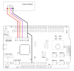
I'm able to flash the "blinky" example code in my custom boards successfully. The path is "nRF5_SDK_15.0.0_a53641a/examples/peripheral/blinky" by connecting its SWD pins to the nRF52 Development Kit's SWD pins as seen in the picture below. The outputs were observed on 3 of the 6 boards while the other 3 failed to respond. ( Please note that all 6 boards flashed successfully)

My questions are:
1. Why 3 of the 6 boards would work, and the other 3 would not?
2. To troubleshoot this, I started desoldering the crystals, first the 32.768 kHz and then the 32 MHz. And still flash happened successfully when no external crystals were connected. Is this behavior normal?
3. Can you suggest particular areas to concentrate on, so I can troubleshoot in an easier way and in lesser time?
Thanks in advance.
Best Regards,
Karan


