This post is older than 2 years and might not be relevant anymore
More Info: Consider searching for newer posts

About nrf52832 automatic frequency conversion output

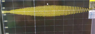
Hello, I want to use nrf52832 to output waveforms as shown above.

Using the Demo1 example in D: Lianxi nordic nRF5_SDK_12.2.0_f012efa examples peripheral pwm_driver, we want to change the frequency output, from large to small, and then from small to large free automatic loop output.

Let's take a look. What's wrong with the frequency? Thank you.

static void demo1_handler(nrf_drv_pwm_evt_type_t event_type)
{
	 uint32_t                   err_code;
    if (event_type == NRF_DRV_PWM_EVT_FINISHED)
    {
            m_demo1_top += 100;
			
			     if(m_demo1_top>=10000)
					 {
						 m_demo1_top=0;
					 }

    }
}


static void demo1(void)
{
    NRF_LOG_INFO("Demo 1\r\n");

    /*
     * This demo plays back a sequence with different values for individual
     * channels (LED 1 - LED 4). Only four values are used (one per channel).
     * Every time the values are loaded into the compare registers, they are
     * updated in the provided event handler. The values are updated in such
     * a way that increase and decrease of the light intensity can be observed
     * continuously on succeeding channels (one second per channel).
     */

    uint32_t                   err_code;
    nrf_drv_pwm_config_t const config0 =
    {
        .output_pins =
        {
            25 | NRF_DRV_PWM_PIN_INVERTED, // channel 0
            //BSP_LED_1 | NRF_DRV_PWM_PIN_INVERTED, // channel 1
            //BSP_LED_3 | NRF_DRV_PWM_PIN_INVERTED, // channel 2
            //BSP_LED_2 | NRF_DRV_PWM_PIN_INVERTED  // channel 3
        },
        .irq_priority = APP_IRQ_PRIORITY_LOWEST,
        .base_clock   = NRF_PWM_CLK_1MHz,
        .count_mode   = NRF_PWM_MODE_UP,
        .top_value    = m_demo1_top,
        .load_mode    = NRF_PWM_LOAD_INDIVIDUAL,
        .step_mode    = NRF_PWM_STEP_AUTO
    };
    err_code = nrf_drv_pwm_init(&m_pwm0, &config0, demo1_handler);
    APP_ERROR_CHECK(err_code);
    m_used |= USED_PWM(0);

    m_demo1_seq_values.channel_0 = 0;
 //   m_demo1_seq_values.channel_1 = 0;
  //  m_demo1_seq_values.channel_2 = 0;
  //  m_demo1_seq_values.channel_3 = 0;
    m_demo1_phase                = 0;

    nrf_drv_pwm_simple_playback(&m_pwm0, &m_demo1_seq, 1,
                                NRF_DRV_PWM_FLAG_LOOP);
}

Parents
  • Hi,

    You can modify demo1 to increase and decrease the ouput just in one channel. See the following code:

    static void demo1_handler(nrf_drv_pwm_evt_type_t event_type)
    {
    
    	
        if (event_type == NRF_DRV_PWM_EVT_FINISHED)
        {
    //        uint8_t channel    = m_demo1_phase >> 1;
            bool    down       = m_demo1_phase & 1;
            bool    next_phase = false;
    
            uint16_t * p_channels = (uint16_t *)&m_demo1_seq_values;
     //     uint16_t   value      = p_channels[channel];
    				uint16_t value = m_demo1_seq_values.channel_0;
            if (down)
            {
                value -= m_demo1_step;
                if (value == 0)
                {
                    next_phase = true;
                }
            }
            else
            {
                value += m_demo1_step;
                if (value >= m_demo1_top)
                {
                    next_phase = true;
                }
            }
    				m_demo1_seq_values.channel_0 = value;
            //p_channels[channel] = value;
    
            if (next_phase)
            {
                if (++m_demo1_phase >= 2 * NRF_PWM_CHANNEL_COUNT)
                {
                    m_demo1_phase = 0;
                }
            }
        }
    }
    
    
    static void demo1(void)
    {
        NRF_LOG_INFO("Demo 1\r\n");
    
        /*
         * This demo plays back a sequence with different values for individual
         * channels (LED 1 - LED 4). Only four values are used (one per channel).
         * Every time the values are loaded into the compare registers, they are
         * updated in the provided event handler. The values are updated in such
         * a way that increase and decrease of the light intensity can be observed
         * continuously on succeeding channels (one second per channel).
         */
    
        uint32_t                   err_code;
        nrf_drv_pwm_config_t const config0 =
        {
            .output_pins =
            {
                BSP_LED_0 | NRF_DRV_PWM_PIN_INVERTED, // channel 0
    //            BSP_LED_1 | NRF_DRV_PWM_PIN_INVERTED, // channel 1
    //            BSP_LED_3 | NRF_DRV_PWM_PIN_INVERTED, // channel 2
    //            BSP_LED_2 | NRF_DRV_PWM_PIN_INVERTED  // channel 3
            },
            .irq_priority = APP_IRQ_PRIORITY_LOWEST,
            .base_clock   = NRF_PWM_CLK_1MHz,
            .count_mode   = NRF_PWM_MODE_UP,
            .top_value    = m_demo1_top,
            .load_mode    = NRF_PWM_LOAD_INDIVIDUAL,
            .step_mode    = NRF_PWM_STEP_AUTO
        };
        err_code = nrf_drv_pwm_init(&m_pwm0, &config0, demo1_handler);
        APP_ERROR_CHECK(err_code);
        m_used |= USED_PWM(0);
    
        m_demo1_seq_values.channel_0 = 0;
    //    m_demo1_seq_values.channel_1 = 0;
    //    m_demo1_seq_values.channel_2 = 0;
    //    m_demo1_seq_values.channel_3 = 0;
        m_demo1_phase                = 0;
    
        nrf_drv_pwm_simple_playback(&m_pwm0, &m_demo1_seq, 1,
                                    NRF_DRV_PWM_FLAG_LOOP);
    }


    Best Regards,

    Marjeris

  • Hello, thank you for your reply, this is changing the duty cycle, and I want to change the frequency. Is there any way?

Reply Children
Related