This post is older than 2 years and might not be relevant anymore
More Info: Consider searching for newer posts

About nrf52832 automatic frequency conversion output

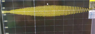
Hello, I want to use nrf52832 to output waveforms as shown above.

Using the Demo1 example in D: Lianxi nordic nRF5_SDK_12.2.0_f012efa examples peripheral pwm_driver, we want to change the frequency output, from large to small, and then from small to large free automatic loop output.

Let's take a look. What's wrong with the frequency? Thank you.

static void demo1_handler(nrf_drv_pwm_evt_type_t event_type)
{
	 uint32_t                   err_code;
    if (event_type == NRF_DRV_PWM_EVT_FINISHED)
    {
            m_demo1_top += 100;
			
			     if(m_demo1_top>=10000)
					 {
						 m_demo1_top=0;
					 }

    }
}


static void demo1(void)
{
    NRF_LOG_INFO("Demo 1\r\n");

    /*
     * This demo plays back a sequence with different values for individual
     * channels (LED 1 - LED 4). Only four values are used (one per channel).
     * Every time the values are loaded into the compare registers, they are
     * updated in the provided event handler. The values are updated in such
     * a way that increase and decrease of the light intensity can be observed
     * continuously on succeeding channels (one second per channel).
     */

    uint32_t                   err_code;
    nrf_drv_pwm_config_t const config0 =
    {
        .output_pins =
        {
            25 | NRF_DRV_PWM_PIN_INVERTED, // channel 0
            //BSP_LED_1 | NRF_DRV_PWM_PIN_INVERTED, // channel 1
            //BSP_LED_3 | NRF_DRV_PWM_PIN_INVERTED, // channel 2
            //BSP_LED_2 | NRF_DRV_PWM_PIN_INVERTED  // channel 3
        },
        .irq_priority = APP_IRQ_PRIORITY_LOWEST,
        .base_clock   = NRF_PWM_CLK_1MHz,
        .count_mode   = NRF_PWM_MODE_UP,
        .top_value    = m_demo1_top,
        .load_mode    = NRF_PWM_LOAD_INDIVIDUAL,
        .step_mode    = NRF_PWM_STEP_AUTO
    };
    err_code = nrf_drv_pwm_init(&m_pwm0, &config0, demo1_handler);
    APP_ERROR_CHECK(err_code);
    m_used |= USED_PWM(0);

    m_demo1_seq_values.channel_0 = 0;
 //   m_demo1_seq_values.channel_1 = 0;
  //  m_demo1_seq_values.channel_2 = 0;
  //  m_demo1_seq_values.channel_3 = 0;
    m_demo1_phase                = 0;

    nrf_drv_pwm_simple_playback(&m_pwm0, &m_demo1_seq, 1,
                                NRF_DRV_PWM_FLAG_LOOP);
}

Parents
  • Hi,

    You can modify demo1 to increase and decrease the ouput just in one channel. See the following code:

    static void demo1_handler(nrf_drv_pwm_evt_type_t event_type)
    {
    
    	
        if (event_type == NRF_DRV_PWM_EVT_FINISHED)
        {
    //        uint8_t channel    = m_demo1_phase >> 1;
            bool    down       = m_demo1_phase & 1;
            bool    next_phase = false;
    
            uint16_t * p_channels = (uint16_t *)&m_demo1_seq_values;
     //     uint16_t   value      = p_channels[channel];
    				uint16_t value = m_demo1_seq_values.channel_0;
            if (down)
            {
                value -= m_demo1_step;
                if (value == 0)
                {
                    next_phase = true;
                }
            }
            else
            {
                value += m_demo1_step;
                if (value >= m_demo1_top)
                {
                    next_phase = true;
                }
            }
    				m_demo1_seq_values.channel_0 = value;
            //p_channels[channel] = value;
    
            if (next_phase)
            {
                if (++m_demo1_phase >= 2 * NRF_PWM_CHANNEL_COUNT)
                {
                    m_demo1_phase = 0;
                }
            }
        }
    }
    
    
    static void demo1(void)
    {
        NRF_LOG_INFO("Demo 1\r\n");
    
        /*
         * This demo plays back a sequence with different values for individual
         * channels (LED 1 - LED 4). Only four values are used (one per channel).
         * Every time the values are loaded into the compare registers, they are
         * updated in the provided event handler. The values are updated in such
         * a way that increase and decrease of the light intensity can be observed
         * continuously on succeeding channels (one second per channel).
         */
    
        uint32_t                   err_code;
        nrf_drv_pwm_config_t const config0 =
        {
            .output_pins =
            {
                BSP_LED_0 | NRF_DRV_PWM_PIN_INVERTED, // channel 0
    //            BSP_LED_1 | NRF_DRV_PWM_PIN_INVERTED, // channel 1
    //            BSP_LED_3 | NRF_DRV_PWM_PIN_INVERTED, // channel 2
    //            BSP_LED_2 | NRF_DRV_PWM_PIN_INVERTED  // channel 3
            },
            .irq_priority = APP_IRQ_PRIORITY_LOWEST,
            .base_clock   = NRF_PWM_CLK_1MHz,
            .count_mode   = NRF_PWM_MODE_UP,
            .top_value    = m_demo1_top,
            .load_mode    = NRF_PWM_LOAD_INDIVIDUAL,
            .step_mode    = NRF_PWM_STEP_AUTO
        };
        err_code = nrf_drv_pwm_init(&m_pwm0, &config0, demo1_handler);
        APP_ERROR_CHECK(err_code);
        m_used |= USED_PWM(0);
    
        m_demo1_seq_values.channel_0 = 0;
    //    m_demo1_seq_values.channel_1 = 0;
    //    m_demo1_seq_values.channel_2 = 0;
    //    m_demo1_seq_values.channel_3 = 0;
        m_demo1_phase                = 0;
    
        nrf_drv_pwm_simple_playback(&m_pwm0, &m_demo1_seq, 1,
                                    NRF_DRV_PWM_FLAG_LOOP);
    }


    Best Regards,

    Marjeris

  • Hello, thank you for your reply, this is changing the duty cycle, and I want to change the frequency. Is there any way?

  • Hi,

    Sorry my bad, I thought you meant duty cycle. Take a look at Rune's answer in this similar devzone post.

    With the PWM hardware the top value is set during init so you will need to uninit and init each time you change it.

    I will need some time to test the code for a solution using timers, GPIOTE and PPI if you want to go that way. 

    Best Regards,

    Marjeris


Reply Children
Related