This post is older than 2 years and might not be relevant anymore
More Info: Consider searching for newer posts

nRF52840 dongle question

Hello,

I am trying to use IAR examples to debug some of the examples provided in the SDK.

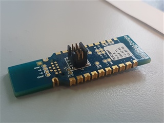
I am only using examples that support the pca10059 dongle.

One example is the peripheral/Blinky.

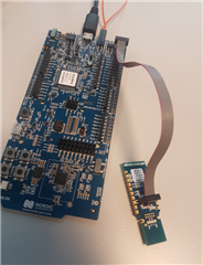
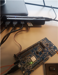
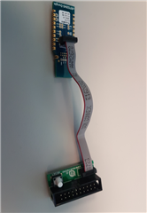
The J-Link with IAR debugger is working. My problem is that I cannot flash the part and debug it because it is already programmed with USB bootloader.

What do I need to do please in order to be able to flash the dongle and debug it succefuly?

Thank you.

Mohammad Karaki

Parents
  • Hi Andreas,

    I installed JTAG connector and used IAr J-Link to do that.

    My question should be is how to debug any of the examples provided for the dongle?

    The dongle uses a bootloader and I am not sure how to download the example to the dongle and be able to debug it using IAR workbench.

    Is there a way to do that , whether using this method or any other one you may suggest?

    Thank you.

    Mohammad

  • Hi Andreas,

    The J-link is working fine with the dongle. My problem is how to bypass the bootloader so I can debug the code on the dongle. 

    If you have another method to debug examples on the dongle please let me know about it.

    Thanks again.

    Mohammad

  • Hi again.

    You just have to reprogram it with your IAR J-Link. However, if you do a full flash erase (which includes erasing the UICR), you will have problems unless you have a debugger which has a levelshifter.

    This is because in the UICR there is a register called REGOUT0, which sets the voltage (standard value 1.8 V). And you need to have 3.0V in order to program the chip.

    To avoid this:

     - Never delete the UICR, and if you do delete UICR you should need to make sure that you set REGOUT0 to 3.0V before you reset.

    - Or, use a debugger which supports level shifting (for example the J-Link Pro, but this debugger is expensive).

    That's why I asked which IAR J-Link you have.

    - Andreas

  • Hi AndreasF,

    Ok. Thanks.

    The SDK provides some examples to support the dongle using IAR.

    One example is:

     ......\nRF5_SDK_for_Thread_and_Zigbee_2.0.0_29775ac\examples\peripheral\blinky


    How can I debug such examples on the dongle using the JTAG or the USB  driver of the dongle itself?

    Can you walk me through such steps?

    Greatly appreciated.

    Regards,

    Mohammad

Reply
  • Hi AndreasF,

    Ok. Thanks.

    The SDK provides some examples to support the dongle using IAR.

    One example is:

     ......\nRF5_SDK_for_Thread_and_Zigbee_2.0.0_29775ac\examples\peripheral\blinky


    How can I debug such examples on the dongle using the JTAG or the USB  driver of the dongle itself?

    Can you walk me through such steps?

    Greatly appreciated.

    Regards,

    Mohammad

Children
  • Hi.

    You need to solder a ARM Cortex JTAG SWD 10pin Connector onto footprint P1, and either connect that to a external debugger or a development kit, like this:

    Connected to a development kit it looks like this:

    And connect the Dongle to a USB port

    Note: it is really important that the voltage on the nRF52840 Dongle matches the nRF52832 DK if you do it this way.

    If you want to use an external debugger, you could connect it like this:

    And connected the Dongle to a USB port:

    And also connected it to a debugger (I'm using the J-Link BASE here)

    Then you just have to use the IDE you wish to use to debug.

    - Andreas

  • Hi Andreasf,

    I have done that already. I told you I was able to use IAR with Jlink to download an example to the dongle. The problem is that I had to erase the dongle program, retarget the example to address 0x0000000 instead of the 0x1000000 the dongle uses with its bootloader.

    What I need from you, again, is to try to use one of the examples provided and succefuly debug it with the IAR workbench and let me know how you did it.

    After downloading the code, the pointer should break at "main"

    Thank you.

    Mohammad

  • Hi.

    Which specific example are you looking at? Please give me the exact path in your SDK folder.

    The pca10059 examples have an offset, so if you have loaded a pca10059 example, you could have placed it in the wrong place.

    Note that the peripherals examples does not require a SoftDevice.

    - Andreas

  • Hi,

     ......\nRF5_SDK_for_Thread_and_Zigbee_2.0.0_29775ac\examples\peripheral\blinky

    What about the examples that require softdevice? How do I load them into the dongle?

    Thanks.

    Mohammad

  • Hi.

    If you look at the linker script for that project, you can see the following at the top of the file:

    (i looked at the file: nRF5_SDK_for_Thread_and_Zigbee_2.0.0_29775ac\examples\peripheral\blinky\pca10059\mbr\armgcc\blinky_gcc_nrf52.ld)

    MEMORY
    {
      FLASH (rx) : ORIGIN = 0x1000, LENGTH = 0xff000
      RAM (rwx) :  ORIGIN = 0x20000008, LENGTH = 0x3fff8
    }

    As you see, ORGIN =0x1000, compaired to the pca10056 (for nRF52840 Development Kit):

    MEMORY
    {
      FLASH (rx) : ORIGIN = 0x0, LENGTH = 0x100000
      RAM (rwx) :  ORIGIN = 0x20000000, LENGTH = 0x40000
    }

    Which has ORGIN = 0x0.

    So the application is placed in an area which is not run, because you have deleted the bootloader.

    You have to change this address to 0x0.

    A project which uses the SoftDevice have another origin, like this:

    MEMORY
    {
      FLASH (rx) : ORIGIN = 0x26000, LENGTH = 0xda000
      RAM (rwx) :  ORIGIN = 0x200022e0, LENGTH = 0x3dd20
    }

    The SoftDevice knows that there is an offset and the origin of the application is at 0x2600, so it will start that application.

    If you wish to use a program which requires SoftDevice, you also have to load the SoftDevice .hex file (S140 v6.1.0 found in nRF5_SDK_15.2.0_9412b96\components\softdevice\s140\hex)

    - Andreas

Related