This post is older than 2 years and might not be relevant anymore
More Info: Consider searching for newer posts

How to Run DTM on nRF52840 development kit using MT8852B?

Hi all,


I have a nRF52840 development kit and flashed (I believed it flashed successfully) with direct test mode .hex file from SDK 15.2. What I facing was not able to run any test from MT8852B due to unable to get the unit address from the board. Did anyone tried to run DTM with MT8852B on nRF52840 DK ? Kindly advise

TQ

Parents
  • Hi,


    In order to get DTM running on any bluetooth tester, you would need to use other RXD and TXD pins when using the nRF5x development kit. This is because the UART is by default routed to the SEGGER IC on the devkit, so you will get two UART hosts conflicting the lines.

    If you go into the dtm/direct_test_mode/main.c file, you can change the defines for RXD and TXD in function uart_init().

    After changing these from the default GPIOs P0.06 and P0.08 (flip the kit over to see which GPIOs are unused), you can connect the chosen GPIOs to the bluetooth testers UART. Remember to use BLE 2-Wire when connecting to the Anritsu.

    Kind regards,

    Håkon

  • hi Hakan,

    regarding the Rx & Tx pin, if i only use the J3 usb port as the power source to the nRF52840 chipset, could this good enough to avoid the conflict as you mentioned?? in this case, do i still need to redefine the pin in the main.c file ??

    Another thing, i am using the dtm/direct_test_mode_pca10056.hex file instead of the dtm/main.c file as the source for the test. any different between them?? kindly advice if i am using the correct source code..

    tq

  • Hi,

    I tried again using nrfjprog command tool and segger embedded studio to do programming. The LED on the board is able to blink when i flashed with the example code for led blinking; but it still not able to communicate with anritsu tester after i flashed it with the dtm (examples file) and also your file is not working.

    I noticed above statement from the user guide. It said about U5 & U6 break the connection of the UART, is this a reason why there is no return from the board??

    best regards,

  • Hi,


    Did you connect the GPIOs P0.20 (RXD) and P0.21 (TXD) to your bluetooth tester? Could you post a photo of your setup?

    If you want to use other GPIOs, you can modify the example as I posted in my initial reply.

    New Guy said:
    is this a reason why there is no return from the board??

    If you have cut the solder bridges, and you're using the default GPIOs, then they will be cut.

    By switching the GPIOs to any other free GPIO, you need to manually connect these to your UART adapter.

    Kind regards,

    Håkon

  • Hi,

    i saw in an old post where you mentioned the softdevice has to be disable then only run the DTM. is this softdevice implemented in the dtm.c file ?

    you can find the old post here: https://devzone.nordicsemi.com/f/nordic-q-a/33236/52840-dtm

  • Hi,


    As stated in the answer; DTM and the SoftDevice cannot be enabled at the same time, as they both require the usage of the RADIO peripheral.

    If you have a BLE example, and want to add DTM, you have to ensure that the softdevice is disabled when entering DTM, and vice versa when using the SoftDevice.

    The "direct_test_mode" (DTM) project is standalone and does not require the softdevice.

    Do you still have issues connecting to your bluetooth tester? If yes; could you post info/photos as asked in my former question?


    Kind regards,

    Håkon

  • Hi,

    The problem still there... =.=

    Here is how the connection between the DK board and the Anritsu tester. 

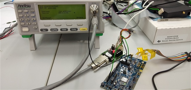
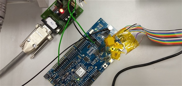
      (Level shifter board)

    BR,

Reply Children
Related