This post is older than 2 years and might not be relevant anymore
More Info: Consider searching for newer posts

NRF24LE1 how to set PWM frequency?

To what values should I set the PWMCON register to so that the PWM0 and PWM1 frequency is output at 20Khz with duty cycle varying between 1 to 2ms. Now specifically I am asking this after reading the data sheet because the tables mentioned are not clearing giving information. How do I decipher the table given here:
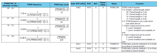
Please clearly disclose information in the data sheets. Also give an example to show how to set to particular frequency and pulse width.

Let me tell you how I decipher this as a newbie. Now CCLK is 16,000,000 for 16Mhz clock. I chose PWM0 as output so bit 0 is 1 and bit 1 is 0. Now I need to find out what PWMCON is so the formula for PWMCON for 20Khz PWM freq will be. (16000000/(255 x 20000))-1 = 160/51 -1 which is approximately 2. Hence PWMCON[5:2] will be 0010. There fore PWMCON will be 11001001 which is 0xC9. But this dint work when I put in this value for PWMCON as the servo did not rotate. Here is my code.

#include "reg24le1.h" // I/O header file for NRF24LE1
#include "hal_delay.h" // header file containing delay functions
 
// main function
void main()
{
int i = 0, j = 0; // loop variable
P0DIR = 0; // Port 0 as output
PWMCON = 0xc9; // enable PWM1
 
// infinte loop
while(1)
{
for(i= 180; i--; i > 0)
{
PWMDC0 = i ; // change duty cycle
delay_ms(10); // delay of 10 ms
}
 
 
}
 
}

Parents
  • How do we get a 50Hz PWM wave? What changes should I make to the code.

  • It does not go that far down. From the documentation:

    The following table shows how the PWM frequency (or period length) and the PWM duty cycle are controlled
    by the PWM SFR registers. PWM frequency range is approximately 4 kHz-254 kHz.

  • I will try to modify my own AVR code for this and develop a library. I need you to tell the equivalent statements for the timers in NRF24LE1.

    1st section of code

    void servoStart(void) 
    { 
        // Outputs 
    	//if(servouniv<=7)
        SERVO_DDR |= SERVO_MASK; 
    	//if(servouniv>7 && servouniv<=15)
    	SERVO_DDR1 |= SERVO_MASK;
        // Setupt a first compare match 
        OCR1A = TCNT1 + US2TIMER1(100); 
        // start timer 1 with no prescaler 
        TCCR1B = (1 << CS10);       
        // Enable interrupt 
        TIMSK |= (1 << OCIE1A); 
    } 
    

    2nd section of code

    ISR(TIMER1_COMPA_vect) 
    { 
        static uint16_t nextStart; 
        static int servo=-1; 
    	static uint8_t servo1;
        static bool outputHigh = true; 
        uint16_t currentTime = OCR1A; 
        uint8_t mask = servoOutMask[servo]; 
    //	uint8_t mask1 = servoOutMask1[servo]; 
        
    	servouniv=servo;
    	
        if (outputHigh)
    	{ 
    
    		if(servo>=6)
    		SERVO_PORT1|= mask;
    		if(servo<=5)
            SERVO_PORT |= mask; 
    		
    		
    		//}
    		/*if((servo>7)&&(servo<=15))
    		{
    		SERVO_PORT1 |= mask1;
    		}*/
            // Set the end time for the servo pulse 
    		
            OCR1A = currentTime + servoTime[servo]; 
    		//if((servo>7)&&(servo<=15))
    		//OCR1A = currentTime + servoTime[servo]; 
            nextStart = currentTime + US2TIMER1(SERVO_TIME_DIV); 
        } 
    	
    else
    	{ 
    		//.....// 
            OCR1A = nextStart; 
        } 
        outputHigh = !outputHigh; 
        }
        

    Please let me know the equivalent statements

  • For the first section of the code I did this.

    // Setupt a first compare match 
        //OCR1A = TCNT1 + US2TIMER1(100);
        short combined = (TH1 << 8 )| TL1;
    	  //CC1S = (CCH1 << 8) | CCL2;
        short CC1S = combined + US2TIMER1(100); 
        // start timer 1 with no prescaler 
        //TCCR1B = (1 << CS10);
    		TR0 = 1;	
        // Enable interrupt 
        //TIMSK |= (1 << OCIE1A);
    		ET0 = 1;	

    Is this right?

  • Hi,


    If you want to generate a 1 ms pulse then wait 20 ms, you can do something like this in your ISR routine:

    void t0_interrupt(void) interrupt 1
    {       
      // Timer increments every 2*12 CPU clock cycles
      // Timer starts counting down from 65535
      // 666 * 1,5 us = 999 us
      static bit timer_state;
      static bit gpio_is_set;
      uint16_t timer_val;
      
      if (timer_state == false)
      {
        timer_val = 0xFFFF - 666;
        
        if (gpio_is_set == 1) 
        {
            timer_state = true;
        }
        gpio_is_set ^=1;
        P10 ^= 1;
      }
      // Wait a given time, in this case 19 ms, before pulsing the pin again.
      else
      {
        // Need to adjust for the prior timer event
        timer_val = 0xFFFF - 13333 + 2*666;
        timer_state = false;
      }
      TL0 = (uint8_t) (timer_val & 0xFF);
      TH0 = (uint8_t) ((timer_val >> 8) & 0xFF);
    }

    You need to set the LED, wait x ms, then turn it off. Then you extend the timer to be 18 ms (20 ms total), then re-do the whole procedure.

    Could you try that?


    Kind regards,

    Håkon

  • If I have to control two servos with a single timer then how do I do that? Please let me know. I am trying to get a second servo working. Now the pulse width for both of the servos should be unique so that I can hold these servos at independent angles..

  • Will this code do the trick

    void t0_interrupt(void) interrupt 1
    {       
      // Timer increments every 2*12 CPU clock cycles
      // Timer starts counting down from 65535
    	
      // 666 * 1,5 us = 999 us
      static bit timer_state1;
      static bit gpio_is_set1;
      uint16_t timer_val1;
    	
    	static bit timer_state1;
      static bit gpio_is_set1;
      uint16_t timer_val2;
      
      if (timer_state1 == 0)
      {
        timer_val1 = 0xFFFF - 666;
        
        if (gpio_is_set1 == 1) 
        {
            timer_state1 = 1;
        }
        gpio_is_set1 ^=1;
        P01 = 1;
      }
    	// 666 * 1,5 us = 1500 us
    	if(timer_state2 == 0)
    	{
    		timer_val1 = OxFFFF-666-999;
    		if (gpio_is_set2 == 1) 
        {
            timer_state2 = 1;
        }
        gpio_is_set1 ^=1;
    		PO2 = 1;
    	}
      // Wait a given time, in this case 19 ms, before pulsing the pin again.
      else
      {
        // Need to adjust for the prior timer event
        timer_val1 = 0xFFFF - 13333 + 2*666;
    		P01 = 0;
        timer_state1 = 0;
    		
    		timer_val1 = 0xFFFF - 13333 + 2*666 *2*999;
    		P02 = 0;
        timer_state2 = 0;
      }
      TL0 = (uint8_t) (timer_val1 & 0xFF);
      TH0 = (uint8_t) ((timer_val1 >> 8) & 0xFF);
    }

Reply
  • Will this code do the trick

    void t0_interrupt(void) interrupt 1
    {       
      // Timer increments every 2*12 CPU clock cycles
      // Timer starts counting down from 65535
    	
      // 666 * 1,5 us = 999 us
      static bit timer_state1;
      static bit gpio_is_set1;
      uint16_t timer_val1;
    	
    	static bit timer_state1;
      static bit gpio_is_set1;
      uint16_t timer_val2;
      
      if (timer_state1 == 0)
      {
        timer_val1 = 0xFFFF - 666;
        
        if (gpio_is_set1 == 1) 
        {
            timer_state1 = 1;
        }
        gpio_is_set1 ^=1;
        P01 = 1;
      }
    	// 666 * 1,5 us = 1500 us
    	if(timer_state2 == 0)
    	{
    		timer_val1 = OxFFFF-666-999;
    		if (gpio_is_set2 == 1) 
        {
            timer_state2 = 1;
        }
        gpio_is_set1 ^=1;
    		PO2 = 1;
    	}
      // Wait a given time, in this case 19 ms, before pulsing the pin again.
      else
      {
        // Need to adjust for the prior timer event
        timer_val1 = 0xFFFF - 13333 + 2*666;
    		P01 = 0;
        timer_state1 = 0;
    		
    		timer_val1 = 0xFFFF - 13333 + 2*666 *2*999;
    		P02 = 0;
        timer_state2 = 0;
      }
      TL0 = (uint8_t) (timer_val1 & 0xFF);
      TH0 = (uint8_t) ((timer_val1 >> 8) & 0xFF);
    }

Children
Related