Hi,
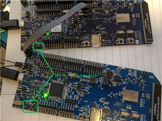
I plan to design my own hardware based around nRF9160. Prior to this, I want to verify that I can use the nRF9160DK as a debugger for my own board. As an initial test, I plan to use two nRF9160 DK boards, one as a target and one as a debugger. I would like to verify the set up for this please.
On the "debugger" nrf9160DK, I connect a USB cable into J4.
I connected a 10pin cable from P22 (Debug Out) on the debugger board into P3 (nrf91 Debug in) on the target board.
On the target board, I select "nRF only" via SW1.
Connect a second USB cable to J4 on the target board. This will provide power and VCOM on the target board.
So, I have three questions.
1. Are my connections above correct?
2. Are there any other switches or settings I need to adjust
3. With only the target board connected to the PC, and SW1, nRF ONLY selected, I don't see any serial data over the USB connector. I know my code is running, as it toggles a GPIO pin which I can monitor. Where is the serial port visible when the target is in nrf only mode?
Thanks,
Rod


