Hi Everyone,
I have a custom board with nRF52840 and am testing out basic GPIO functionalities with some LEDs. In the board, the LED cathode is connected to nRF52840 GPIO and the anode is connected to 3.3V; so, I need to pull the GPIO to LOW to switch on an LED and pull the GPIO to HIGH to switch off an LED.
The GPIOs that I'm using nRF52840 can output logic HIGH and LOW; however, the logic level for LOW is at 1.76 V (or 1.44 V) which doesn't make sense to me - logic level for HIGH is okay at 3.3V. As a result of having LOW at 1.76V instead of 0V, the LEDs are dimmer than they are supposed to be. On a few occasions when I uploaded misconfigured firmware, I've seen the LEDs blink at their expected brightness, but I can't tell what's going wrong here.
I've tested the same code on nRF52840DK and the output seems to be fine: the GPIOs on nRF52840 output 0V and 3.3V for LOW and HIGH, respectively. I'm not sure what's going wrong on the custom board, however; the connections are fairly straightforward.
I'm running the code using Segger Embedded Studio. The SWD on nRF52840DK is used to flash the custom board as it does not contain an on-board debugger.
The code I'm using to set up the LEDs is as follows:
#define LED1 NRF_GPIO_PIN_MAP(0, 29)
#define LED2 NRF_GPIO_PIN_MAP(0, 2)
#define LED3 NRF_GPIO_PIN_MAP(1, 15)

#define OUT1 NRF_GPIO_PIN_MAP(0, 31)

static void buttons_leds_init()
{
  ret_code_t err_code;

  err_code = nrf_drv_gpiote_init();
  APP_ERROR_CHECK(err_code);

  nrf_drv_gpiote_out_config_t out_config = GPIOTE_CONFIG_OUT_SIMPLE(true);

  err_code = nrf_drv_gpiote_out_init(OUT1, &out_config);
  APP_ERROR_CHECK(err_code);

  out_config = GPIOTE_CONFIG_OUT_SIMPLE(false);

  err_code = nrf_drv_gpiote_out_init(LED1, &out_config);
  APP_ERROR_CHECK(err_code);
  err_code = nrf_drv_gpiote_out_init(LED2, &out_config);
  APP_ERROR_CHECK(err_code);
  err_code = nrf_drv_gpiote_out_init(LED3, &out_config);
  APP_ERROR_CHECK(err_code);


}
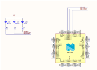
Here's the schematics for the connections used.