This post is older than 2 years and might not be relevant anymore
More Info: Consider searching for newer posts

nRF52840 Logic LOW is not 0 Volts on Custom Board

Hi Everyone,

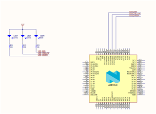
I have a custom board with nRF52840 and am testing out basic GPIO functionalities with some LEDs. In the board, the LED cathode is connected to nRF52840 GPIO and the anode is connected to 3.3V; so, I need to pull the GPIO to LOW to switch on an LED and pull the GPIO to HIGH to switch off an LED.

The GPIOs that I'm using nRF52840 can output logic HIGH and LOW; however, the logic level for LOW is at 1.76 V (or 1.44 V) which doesn't make sense to me - logic level for HIGH is okay at 3.3V. As a result of having LOW at 1.76V instead of 0V, the LEDs are dimmer than they are supposed to be. On a few occasions when I uploaded misconfigured firmware, I've seen the LEDs blink at their expected brightness, but I can't tell what's going wrong here.

I've tested the same code on nRF52840DK and the output seems to be fine: the GPIOs on nRF52840 output 0V and 3.3V for LOW and HIGH, respectively. I'm not sure what's going wrong on the custom board, however; the connections are fairly straightforward.

I'm running the code using Segger Embedded Studio. The SWD on nRF52840DK is used to flash the custom board as it does not contain an on-board debugger.

The code I'm using to set up the LEDs is as follows:

#define LED1 NRF_GPIO_PIN_MAP(0, 29)
#define LED2 NRF_GPIO_PIN_MAP(0, 2)
#define LED3 NRF_GPIO_PIN_MAP(1, 15)

#define OUT1 NRF_GPIO_PIN_MAP(0, 31)

static void buttons_leds_init()
{
  ret_code_t err_code;

  err_code = nrf_drv_gpiote_init();
  APP_ERROR_CHECK(err_code);

  nrf_drv_gpiote_out_config_t out_config = GPIOTE_CONFIG_OUT_SIMPLE(true);

  err_code = nrf_drv_gpiote_out_init(OUT1, &out_config);
  APP_ERROR_CHECK(err_code);
  
  out_config = GPIOTE_CONFIG_OUT_SIMPLE(false);

  err_code = nrf_drv_gpiote_out_init(LED1, &out_config);
  APP_ERROR_CHECK(err_code);
  err_code = nrf_drv_gpiote_out_init(LED2, &out_config);
  APP_ERROR_CHECK(err_code);
  err_code = nrf_drv_gpiote_out_init(LED3, &out_config);
  APP_ERROR_CHECK(err_code);


}

Here's the schematics for the connections used.
Parents
  • What drive strength do you have configured on the pins? If you left them at standard drive that's 0.5mA. At a guess the LEDs drop about 1.5v depending a lot on the LED you've used. At 0.5mA the resistor would drop 0.15v leaving (3.3 - 1.5 - 0.15) = 1.65v which the pin current limiting resistor would drop so the pin would be about 1.65v, not too far from what you're seeing. If you set the pins to high drive, which is 5mA (note there's a limit to how many pins you can do that with) you should see very close to 0v on the pin. 

  • Thanks for your reply.

    After reading your reply and digging up drive strength (here and here), it appears the drive strength was causing the problem since it was left to the default configuration value NRF_GPIO_PIN_S0S1. The LEDs are drawing 20 mA current at Vf = 2V which is above the total 15 mA sinking limit. I guess I'll have to change the LEDs in the next revision.

    I have a few questions based on what we discussed:

    1. What are the different drive modes for? I was surprised to find 8 different drive modes under nrf_gpio_pin_drive_t enum. I couldn't find any clarification on these anywhere.
    2. Although the LEDs lit up brighter after using NRF_GPIO_PIN_H0H1 drive mode, the board would reset immediately irrespective of driving 1 LED or 3 LEDs. Is nRF52840 automatically shutting down due to high current sinking?
Reply
  • Thanks for your reply.

    After reading your reply and digging up drive strength (here and here), it appears the drive strength was causing the problem since it was left to the default configuration value NRF_GPIO_PIN_S0S1. The LEDs are drawing 20 mA current at Vf = 2V which is above the total 15 mA sinking limit. I guess I'll have to change the LEDs in the next revision.

    I have a few questions based on what we discussed:

    1. What are the different drive modes for? I was surprised to find 8 different drive modes under nrf_gpio_pin_drive_t enum. I couldn't find any clarification on these anywhere.
    2. Although the LEDs lit up brighter after using NRF_GPIO_PIN_H0H1 drive mode, the board would reset immediately irrespective of driving 1 LED or 3 LEDs. Is nRF52840 automatically shutting down due to high current sinking?
Children
  • Best thing to do is read the reference documentation which is basically here. It's fairly simple, the modes are just whether a '0' or '1' are driven, if they are driven how hard are they driven and if they aren't driven what are they? The GPIOs for instance have a mode which is a driven '0' but '1' is just high impedence, you'd use a mode like that for a wired-OR. 

    The high drive current limit is pretty accurate, so if you have 3 high drive pins each one is going to get 5mA and that's it, so 15mA total is hard to exceed. So I can't see the chip shutting down due to high current, especially if you are only using 1 of the 3 LEDs, that's 5mA and nothing more. First possibility comes to mind is that your chip power doesn't have enough capacitance and as soon as you suddenly pull even 5mA you drop the voltage under the brownout level. If you're testing with bench power that ought not to happen, if you're using a coin cell, it certainly could. I know that the user Abystomalabs has posted some excellent replies here about the size of decoupling capacitors when using a coin cell and I seem to remember he advocates for a couple of uF near the power pin. 

    If not that, not sure, try checking the reset reason register to see why it thinks it reset. 

Related