This post is older than 2 years and might not be relevant anymore
More Info: Consider searching for newer posts

Problem using the nRF52840 to interface an ADS1298 via SPI

Hi DevZone,

I am using the nRF52840 to interface an ADS1298 (ECG Chip) via SPI.

I want to test if the communication between the devices are working by:

    -  Sending a RREG (Read From Register) opcode from the nRF52840 to the ADS1298

    -  And then read its ID Register.

The RREG command is two bytes long, and for multi-byte commands the following needs to be done:

    1.  Send the first byte and then wait for 4 * tCLK  before sending the next byte.

    2. The CS (or SS) pin needs to be held low during the entire session for both transfer and receive.

I am trying to test this with the example provided in the nRF5 SDK 15.3 by using this function:

    -  nrf_drv_spi_transfer(&spi, m_tx_buf, m_length, m_rx_buf, m_length);

My problem is that:

    -  I cannot insert a delay between the bytes when using the nrf_drv_spi_tranfer() for multiple byte transfers

    -  If i use separate calls of the nrf_drv_spi_transfer() for each byte, then the CS pin is not held low.

Is there any way I can use this driver to send multiple bytes with a fixed delay between them, without the CS pin going high during the session?

Thank you for reading

Br. Casper

  • The noise very much depends on grounding, and whether the scope probe for a signal is locally grounded very close to the signal source (when probing source) or arrival point (when probing destination on the other board). The probe ground has to be moved each time with the probe, and be connected direct to the ground of the device being probed (not easy unless the board was laid out to accommodate this).

    I am unclear as to what code the last traces are transmitting (MOSI) and receiving (MISO), as it doesn't look like the original request for device type (0x20, 0x01). Can you zoom in on each byte and the responses? I have never had an issue with noise on these parts; how long are the connections between the boards?

  • Yes, it is unclear on the picture. It was only meant to show that the MISO signal was changing with no change in SCLK.

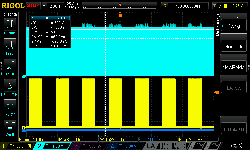
    The problem is not noise, but improper supply of the AVDD voltage on the ADS1298R evaluation board. The voltage was high in two second periods and then low for two seconds, while the DVDD voltage and 3.3VCC being high all the time.
    This was overlooked by my mistake when measuring. Embarrassing. Impressive that the board was able to communicate at all! This was probably also something that threw me off. It was only something I noticed when I did large zoom-out on the scope, and then I decided to look into the power supply again.

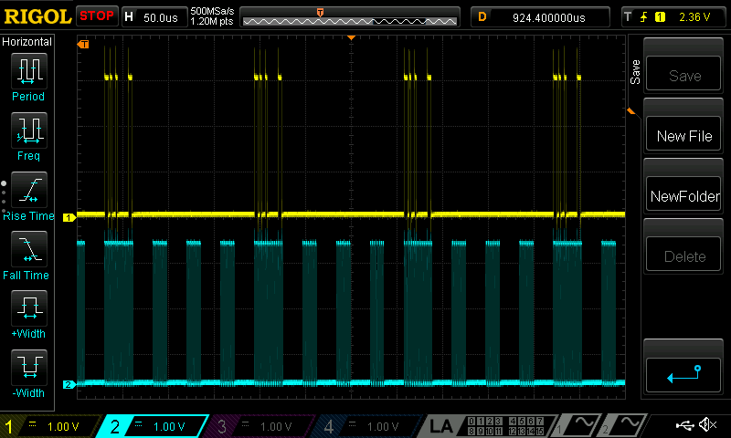
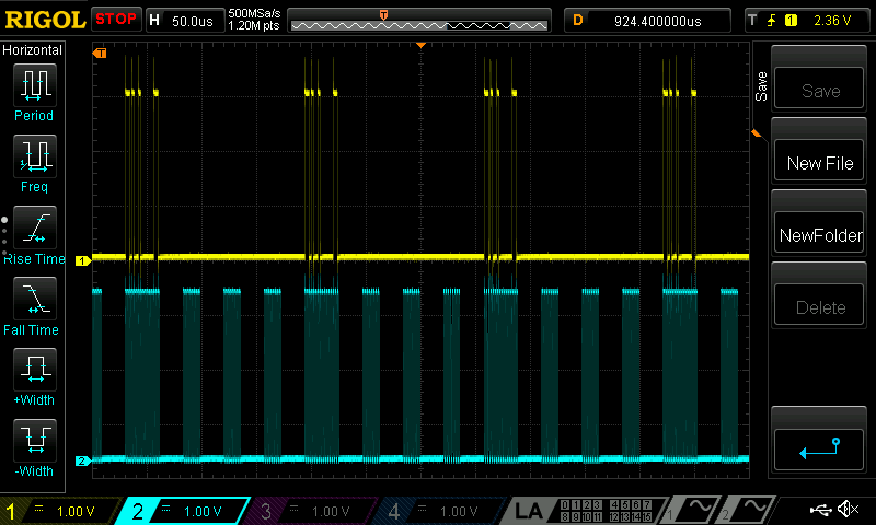
    It is now functioning as expected, returning the correct values on every RREG opcode:

    Thank you very much for your insight and help, it has been amazing!

  • The problem with the ADS1298R evaluation board only answering to a specific sequence of commands, and not consistently has been solved!

    It was a problem with the supply of the AVDD voltage only being supplied for periods of two seconds. This was, embarrassingly, overlooked by me when measuring the voltage supplies earlier in debugging.


    Here is a scope snapshot of the board answering as expected on every RREG opcode.


    Thank you all very much for your help, it is certainly appreciated!

    Br. Casper

  • Hi Casper, I'm currently developing nrf52840 spi communication with ads1198 as a newbie. But, There are so many things I cant solve... firstly how can nrf52840 dk power the ads1198 board? since the board is to be powered by MMb0 DSP board, how did you apply single VDD 3.0V power from nrf52840 to ads board?, so I made my own PCB for ads1198. and I tried to wake up ads1198. But I cant read ID from ADS1198. As I know, DRDY pin should begin pulsing after power up, but there is no response... even though I set START pin pull up, there is no response. Can you help me? or may I get your code for startup ads board?

Related