Hi,
I am using NRF52832 development board , to which i have interfaced LIS3DSH accelerometer sensor(3.3V i2c)
when i configure it for 1600 sampling rate and all the axis enabled , i am not able to get any data .
could anyone help with this problem.
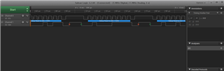
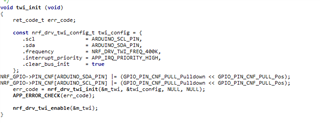
also the I2c clock frequency, as shown in below image, while i am capturing data when i observe in oscilloscope or logic analyzer , clock frequency is showing 200 all the setting is for 400KHz.
what could be the problem for this or is there any other way i need to follow to set the clock to 400KHz.
help me ASAP...
Thank you