Hi,
I've been though some power profiling investigation of my application and incorporated the solutions discussed and here and the hardware solution discussed here but I am using a 1Meg Ohm resistor between the VDD rail and the GPIO PIN. The PIN is the n tied to the ground through a switch.
My development stack is
- An nRF52832 DK
- SDK 15.3.0
- Segger IDE
- The soft device is S112
- JLinkRTTViewer for debug
- I'm using the ble_app_template as my starting point having added the battery service and the link loss service
The power profiler kit that I used from Nordic returned some promising results having worked my way through the instructions below
and support from this board.
Results:
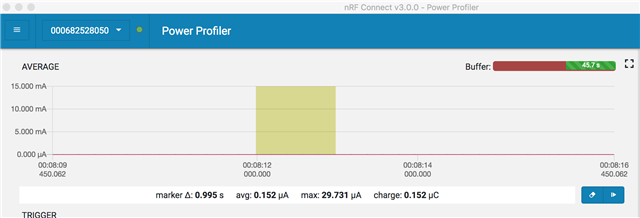
Advertising with PIN 12 pulled to ground

Average whilst in system off was promising as well

and the connection event

My application is quite elementary as it simply monitors a GPIO port and the battery.
- Once a switch on GPIO PIN 12 is pulled to ground it pulls the chip out of sleep and advertises for 30 seconds with a 2 second advertising interval. It then sleeps for 30 seconds and repeat. It is unlikely that the switch will be closed for more than one hour a day.
- I have only two services
- link loss service
- battery service.
- Battery service is set to check the battery level immediately, once "Notify" is initiated by Central, and every 1 hour thereafter.
- If the switch on PIN 12 is opened then the uC goes to sleep.
So getting this far with the power profiling I decided to put a fresh CR 2032 coin cell in my second unit (SB9 not cut) the DK board drained the battery from 100% to 57% overnight to 42% over 24 hours with a maximum of 1 hour of advertising and about 3 connection events.
The power supply information below insists that you never place the USB and coin cell in the system at the same time which I have respected although the diodes should have protects things as there are no solder jumpers on the board at SB11 or SB10.
I also note that my GPIO pin is configured to use GPIOTE PORT event with a NOPULL. As I have a 1M ohm resistor pulling it up to VDD I'm not doing anything silly there am I as per this post?
Questions:
- Is the answer that I should not worry at this point about the battery behaviour of the DK and trust the Power Profiler kit results as I move on to create my custom board?
- Is it because the DK is running a bunch of other stuff on the development board that makes the test obsolete as is discussed here? i.e. for a proper test I should cut solder bridge 29 or wait until my custom board is finished?
Thanks in advance and apologies if a silly question.
Best,
David

